
The RDA5807M – an equivalent of Philips TEA5767 and pin-to-pin compatible – is a single-chip broadcast FM stereo radio tuner with fully integrated synthesizer, IF selectivity and MPX decoder. The tuner uses the CMOS process, support multi-interface and require the least external component. It is completely adjustment-free.
A previous tutorial published here, shows step by step how a Digilent chipKIT uC32 board and Basic I/O shield communicating in I²C protocol with the RDA5807M module can be quite a powerful, yet simple, FM Radio tuner.
Requirements
- Digilent chipKIT uC32 Development board with Digilent Basic I/O shield on top, and power supply


- Class I or II Bluetooth adapter

- JY-MCU Bluetooth Module


- MPIDE software
* Note: The latest MPIDE-0023-wiindows-20140821 does not compile I2C read so you will need to use a test software such as MPIDE-0150-wiindows-20150103
Procedures
a) Install libraries of Basic I/O Shield in MPIDE environment for uC32 board
We assume that you have already installed MPIDE environment.
You will need to know the location of MPIDE sketches folder:
Run MPIDE ![]() . In menu do File -> Preferences find the sketchbook location:
. In menu do File -> Preferences find the sketchbook location:
 Take note of the location of your sketches (MPIDE codes are called “sketches”). In your Windows navigate to where the folder is, and create a directory named ‘Libraries’.
Download from here the zipped file containing libraries and documentation for using the Basic I/O Shield™ with the chipKIT MPIDE and unzip into the Libraries folder you have just created:
 So here we are to go to next procedure
b) Hardware set up
In the first place prepare Digilent chipKIT uC32 board for I²C communication in pins A5 and A6.
On uC32 you must have Jumpers JP6 and JP8 set in the RG3 and RG2 positions.
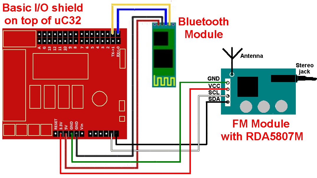
 Install the Basic I/O shield on top of Uc32 as shown on the above image . Connect to the PC with USB cable. USB connection will power the Uc32 and the Basic I/O shield simultaneously. Connect the FM module to uC32 and Basic I/O shield.
The following circuit diagram shows the connections to FM Radio and Bluetooth modules:
 c) Firmware installation
We assume that you have already installed MPIDE environment.
You will need to know the location of MPIDE sketches folder:
Run MPIDE![]()
We will use RDA5807M in Philips TEA5767 mode.
Now do File -> New and write the following Sketch:
/* Code based on Dr Monk's TEA5767 FM Radio Breakout Board for Arduino http://www.doctormonk.com/2012/03/tea5767-fm-radio-breakout-board-for.html A similar but more advanced project have a look at:Arduino FM receiver with TEA5767Adapted for Profilab-Expert 4.0, Digilent chipKIT uc32 and Basic I/O shield by Tayeb Habib tayeb.habib@gmail.com http://redacacia.me For manual mode with potentiometer and remote mode withe Bluetooth */ #include <Wire.h> #include <IOShieldOled.h> unsigned char frequencyH = 0; unsigned char frequencyL = 0; unsigned int frequencyB; double frequency = 0; unsigned char buffer[5]; int LED = 26; int BUTTON = 35; int freq=0; int tensf = 0; int onesf = 0; int dot_tensf = 0; int dot_onesf = 0; int level = 0; int onesl = 0; int tensl = 0; void setup() { Wire.begin(); frequency = 89.5; //starting frequency setFrequency(); Serial.begin(9600); IOShieldOled.begin(); IOShieldOled.displayOn(); pinMode(LED,OUTPUT); pinMode(BUTTON,INPUT); } void loop() { if (digitalRead(BUTTON) == LOW) // manual mode { digitalWrite(LED,LOW); int reading = analogRead(0); frequency = ((double)reading * (108.0 - 87.5)) / 1024.0 + 87.5; setFrequency(); setDisplay(); } if (digitalRead(BUTTON) == HIGH) // remote mode { digitalWrite(LED,HIGH); // send data only when you receive data: while (Serial.available() > 0) { // read the incoming byte: if (Serial.read() == '\n') { frequency = Serial.parseFloat(); setFrequency(); setDisplay(); } } } } void setFrequency() { frequency = ((int)(frequency * 10)) / 10.0; frequencyB = 4 * (frequency * 1000000 + 225000) / 32768; frequencyH = frequencyB >> 8; frequencyL = frequencyB & 0XFF; delay(100); Wire.beginTransmission(0x60); Wire.write(frequencyH); Wire.write(frequencyL); Wire.write(0xB0); Wire.write(0x10); Wire.write((byte)0x00); Wire.endTransmission(); delay(100); } void setDisplay() { Wire.requestFrom(0x60,5); // reading from RDA5807M if (Wire.available()); { for (int i=0; i<5; i++) { buffer[i] = Wire.read(); } // OLED display start up IOShieldOled.displayOn(); // Display information on OLED display IOShieldOled.setCursor(0, 0); IOShieldOled.putString(" FM RADIO"); IOShieldOled.setCursor(0, 2); IOShieldOled.putString("FREQ "); freq = frequency*100; dot_onesf = freq%10; freq = freq/10; dot_tensf = freq%10; freq = freq/10; onesf = freq%10; freq = freq/10; tensf = freq%10; freq = freq/10; //convert data to ASCII tensf = tensf+48; onesf = onesf+48; dot_tensf = dot_tensf+48; dot_onesf = dot_onesf+48; IOShieldOled.setCursor(6, 2); if (tensf <= 48) { IOShieldOled.putString("1"); } else { IOShieldOled.putString(" "); } IOShieldOled.setCursor(7, 2); IOShieldOled.putChar(tensf); IOShieldOled.setCursor(8, 2); IOShieldOled.putChar(onesf); IOShieldOled.setCursor(9, 2); IOShieldOled.putString("."); IOShieldOled.setCursor(10, 2); IOShieldOled.putChar(dot_tensf); // IOShieldOled.setCursor(11, 2); // IOShieldOled.putChar(dot_onesf); IOShieldOled.setCursor(12, 2); IOShieldOled.putString("MHz "); IOShieldOled.setCursor(0, 3); if (buffer[2]&0x80) { IOShieldOled.putString("STE "); } else { IOShieldOled.putString("MON "); } IOShieldOled.setCursor(5, 3); IOShieldOled.putString("SIG"); level = buffer[3]>>4; //extract level of signal // Serial.println(level); onesl = level/10; // Serial.println(onesl); tensl = level/10; tensl = level%10; // Serial.println(tensl); // Convert into ASCII onesl = onesl + 48; tensl = tensl + 48; IOShieldOled.setCursor(9, 3); IOShieldOled.putChar(onesl); IOShieldOled.setCursor(10, 3); IOShieldOled.putChar(tensl); IOShieldOled.setCursor(11, 3); IOShieldOled.putString("/16"); } }
Now first run the code with Verify ![]() to check if it compiles with errors. If does not compile, check the code and compare with the one above. A successful compilation MPIDE will show a message similar to the following:
to check if it compiles with errors. If does not compile, check the code and compare with the one above. A successful compilation MPIDE will show a message similar to the following:
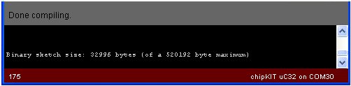 Check that your COM port. In my case it is COM30.
Now click on Upload button ![]() . With a successful upload MPIDE will show a message similar to the following:
. With a successful upload MPIDE will show a message similar to the following:
If all is well you can now tune FM Radio stations.
d) Manual Mode Tuning
The pot on Basic I/O shield is used to tune in the radio stations in manual mode. The following image shows a tuned station in Manual mode i.e. with switch 35 in position OFF:
 e) Remote Mode Tuning
For this a Front Panel for PC must be designed. In our case here I have designed a project in Profilab-Expert 4.0 as shown below:
 You can download the project from here, that s being kept at BitBucket a free and unlimited repository for private usage.
Bluetooth installation in your PC
You must have your Bluetooth adapter duly installed in your PC. My PC’s Bluetooth Sweex adapter shows in my system tray a Bluetooth symbol. After activating Bluetooth, I have the option to find the local Bluetooth connections:
 Do a search, and eventually you will find HC-06 (default name of JY-MCU module, a name that can be changed if required):
 Next, we will connect to JY-MCU Bluetooth module (found in my PC in COM15):

You will need to introduce the password which is ‘1234’:
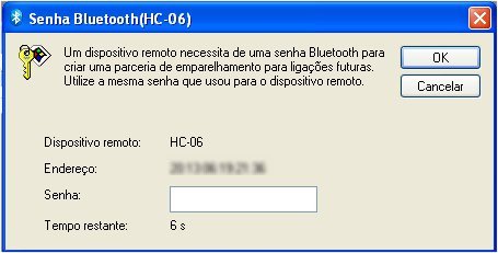 I have blurred the MAC address of my Bluetooth module. After introducing the password, click the OK button. You will see HC-06 connection as paired.
 We next connect HC-06 to the serial port of your PC (in my case it is COM15):
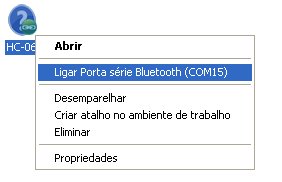 The HC-06 icon will now change to green:
 The LED on JY-MCU will stop blinking and will be ON continuously.
Now make sure that the COM port used by your ProfiLab-Expert 4.0 project is same as the one of your Bluetooth connection. You will note that in my case it COM15. Double click COM icon and change the value in ProfiLab-Expert 4.0 project:
 Now Run the ProfiLab-Expert 4.0 project clicking the Start button
 ![]() or by clicking F9 button of your keyboard.
or by clicking F9 button of your keyboard.
First connect external power supply to set up consisting of the Digilent chipKIT uC32 board and Basic I/O shield.
You will now need to place the switch 35 in Basic I/O in ON position. LED 26 on Basic I/O will be ON. The tuning of Radio station can be done by moving the Tuning Knob on the Front Panel. In our case we have tuned again 92MHz (Radio Amalia in Portugal):
 The following image shows what is going on with the Basic I/O shield:
 The interesting feature of the ProfiLab-Expert 4.0 project is that the Panel remembers the last tuned station.
Our full set up in Remote Mode tuning:

What Next?
1) Use the EEPROM on Basic I/O shield to memorize tuned Radio stations. Memorization can be done remotely on pressing a button on the Front Panel, or a physical button on Basic I/O shield.
2) Get feedback on Front Panel that a station has been tuned in by reading the signal strength on RDA5807M
3) Make a stand-alone application of the Front Panel Project that runs on systems without ProfiLab-Expert 4.0 making use of integrated compiler that can create executable autonomous files.
4) Run the Front Panel from the Web making use of PL Webserver that can be supplied together with ProfiLab-Expert 4.0. The web page can be password protected so your application will not be run by unauthorized persons.

Hi Tayeb, have you ever tried using UECIDE (http://www.uecide.org). I prefer using it over MPIDE 🙂
I actually use UECIDE. MPIDE latest stable version does not compile I2C read. I had to use MPIDE test version as you may see from the tutorial. UECIDE is still quite basic in simple things such as print directly the code.
Hi Tayeb, feel free to email me separately and explain what you mean by that. I’d like to understand more.
Thanks 🙂
Pingback: FM Radio Over I2C and Bluetooth Remote Control with chipKIT uC32 » chipKIT Development Platform
Pingback: Remotely Control FM Radio with a chipKIT uC32 and Basic I/O Shield – Digilent Blog
This is a ggreat post thanks