Introduction
chipKIT Digilent uC32 (or Uno32) and Raspberry Pi are both pretty cheap, almost of the same size, and although they look similar, they are different. The Raspberry Pi is effectively a mini-computer, running a Linux operating system (OS), and the chipKIT is a microcontroller, without a typical typical OS, but purpose-built with important features such as EEPROM, analog inputs and PWM outputs, features that Raspberry Pi does not have. On other hand, Raspberry Pi offers Ethernet connection, USB Master, video and audio outputs, all of these that are not available on chipKIT, can enhance any electronic project.
There is already a marriage between chipKIT and Raspberry Pi, called chipKIT Pi that makes it easy to connect Raspberry Pi to chipIT. The chipKIT Pi board fits nicely on the Raspberry Pi interfacing directly on the IO header of the Raspberry Pi. The board can be used without Raspberry Pi, in stand-alone mode and for this reason there is a DC plug, useful to power the board with a power supply. The ICSP header (JP3) has been added to program the on-board microcontroller PIC32MX250F128B using a Microchip PICkit or a ICD in-circuit debugger/programmer.
Objectives
- Capture the local temperature with Microchip TCN75A temperature sensor on Digilent Basic I/O shield using chipKIT Digilent uC32 board
- Make the reading available through USB port to Raspberry Pi
- Install Telegram in Raspberry Pi
- Make Raspberry Pi with a Python program to read from the USB port, and to accept commands from Telegram
- Write a Lua script to accept commands from Telegram, and to control the previously written Python program
Setup
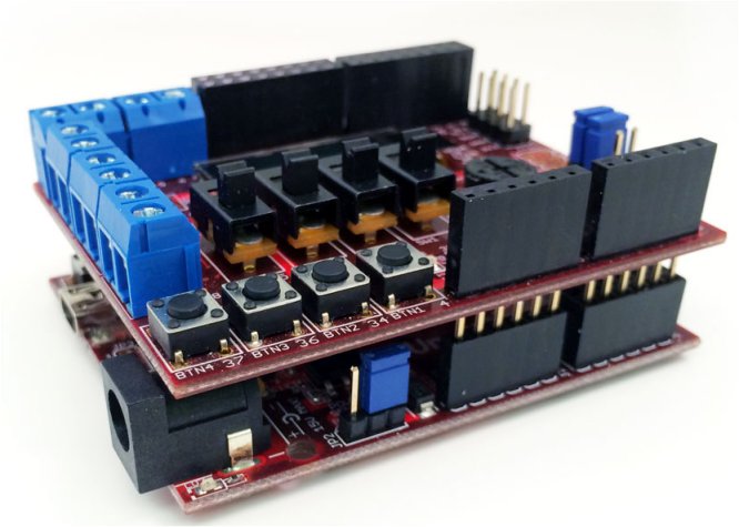
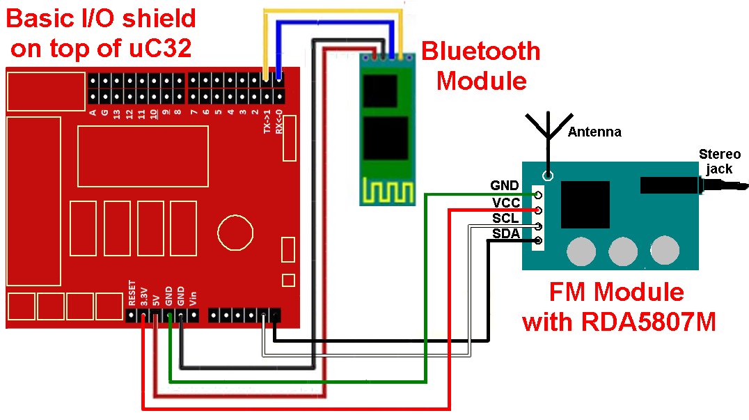
- chipKIT Digilent uC32 with Digilent Basic I/O shield on top, and power supply

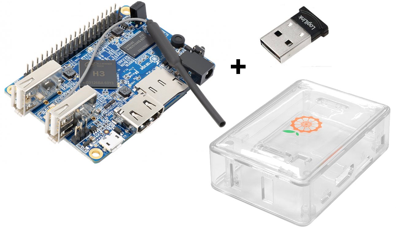
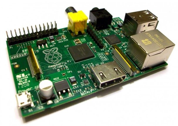
- Raspberry Pi Model B and power supply (and I recommend a powered USB hub)


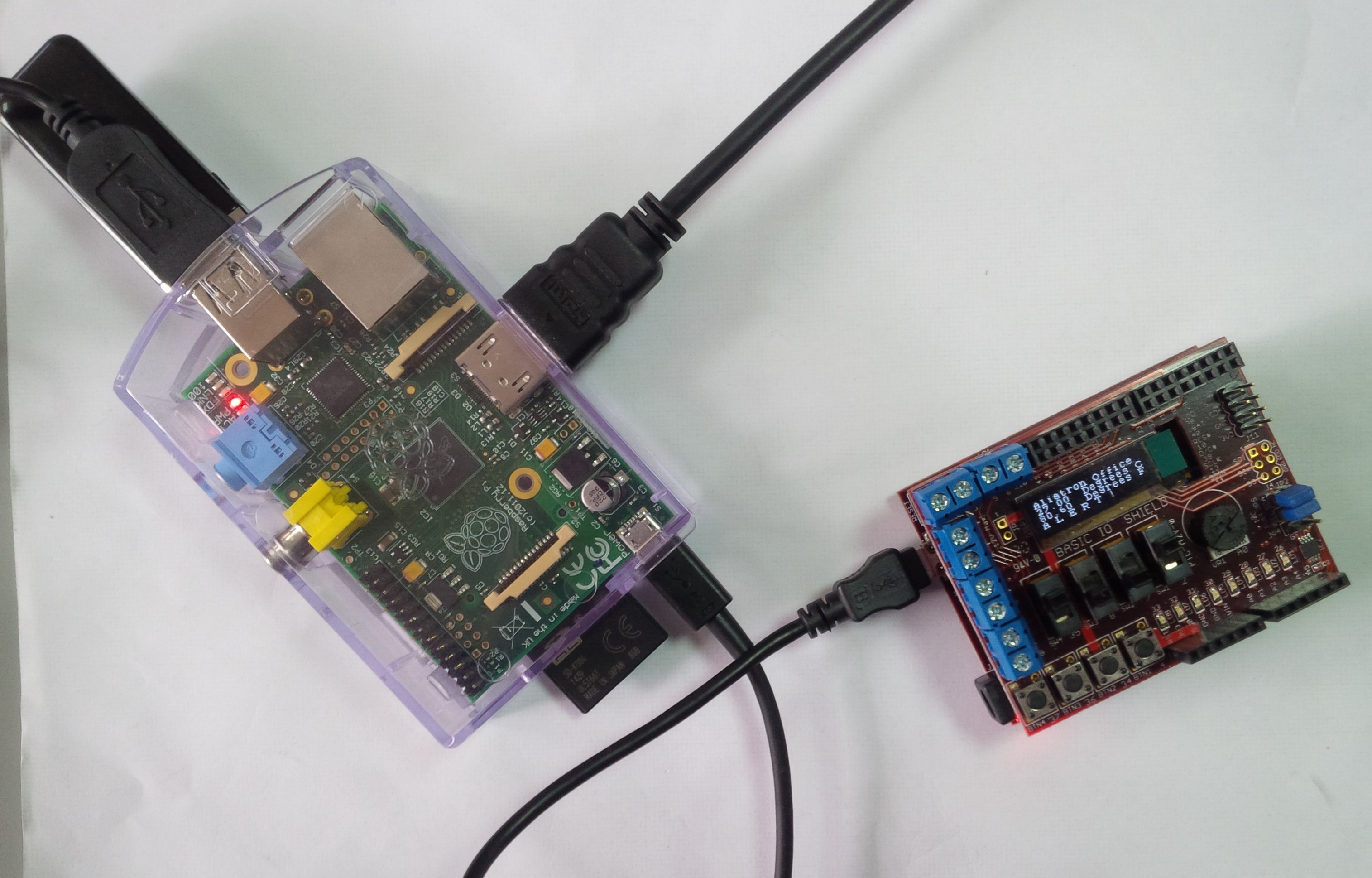
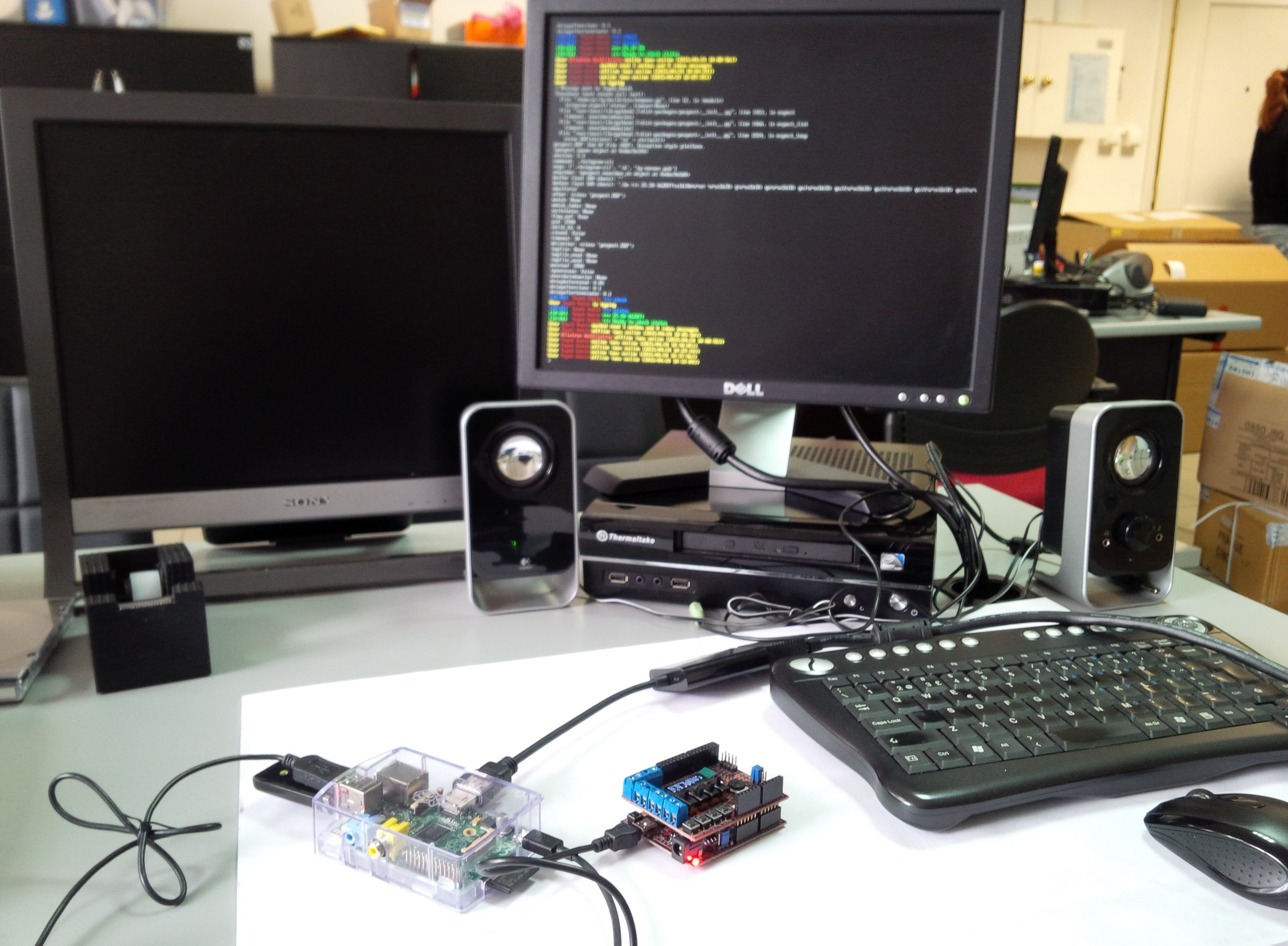
My setup is as following photo shows:

Procedure
a) Install libraries of Basic I/O Shield in MPIDE environment for uC32 board
On uC32 you must have Jumpers JP6 and JP8 set in the RG3 and RG2 positions. Install the Basic I/O shield on top of UNO32 as shown on the above image . Connect to the PC with USB cable. Although USB connection will power uC32 and the Basic I/O shield simultaneously, we will use external power supply to uC32 board.
We assume that you have already installed MPIDE environment.
You will need to know the location of MPIDE sketches folder:
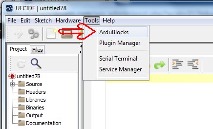
Run MPIDE  . In menu do File -> Preferences find the sketchbook location:
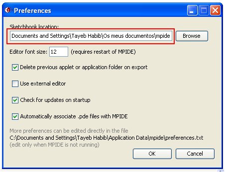 Take note of the location of your sketches (MPIDE codes are called “sketches”). In your Windows navigate to where the folder is, and create a directory named ‘Libraries’.
Download from here the zipped file containing libraries and documentation for using the Basic I/O Shield™ with the chipKIT MPIDE and unzip into the Libraries folder you have just created:
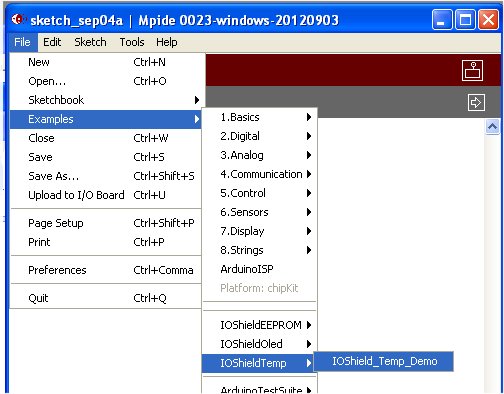
 Now if you do File -> Examples you will see three folders IOShieldEEPROM, IOShieldOled and IOShieldTemp. Open the sketch IOShieldTemp_Demo:
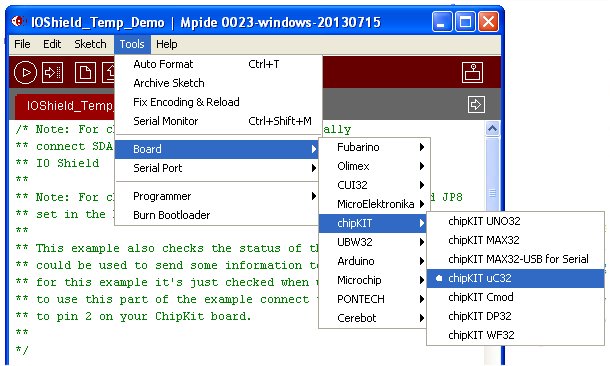
Next choose the board (in our case chipKIT uC32):
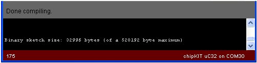
 And choose Serial Port to which the board is connected in Tools >> Serial Port >> (port where UC32 is connected). In my case it is COM30.
Now we are ready to upload the sketch to the board. Click the Upload button  on MPIDE environment.
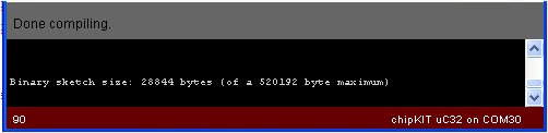
If successful you will see the following results at bottom of MPIDE environment:
 We are now ready to check what is being sent to our COM30 port (your PC’s may be other) in Tools >> Serial Monitor.
A new window will pop up showing the readings sent to your PC’s serial port: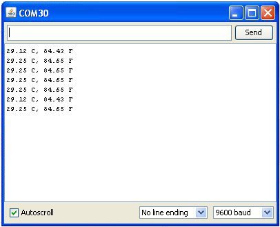 We are getting readings in degrees C and degrees F. Note that Alarm is not displayed even though the temperature is above 24ºC as set in our sketch (you can check – it is clearly written). This happens because in uC32 and Uno32 boards you need to toggle to top the rightmost switch on Basic I/O shield If you do so, ALERT will sent to serial port. You can use the switch to switch off the Alarm by toggling down the switch.
If you are here, the rest will go smoothly.
We will now change this sketch, and adapt it to Raspberry Pi to be read easily by Python. Also, we will add code to show the temperature on OLED display of Basic I/O shield.
/* Original source code at
http://chipkit.net/tag/temperature-sensor/
Modified and adapted by Tayeb Habib tayeb.habib@gmail.com
http://redacacia.me
*/

#include <IOShieldTemp.h>
#include <IOShieldOled.h>
#include <Wire.h>
#define ALERT_PIN 2

int tensc = 0;
int onesc = 0;
int dot_tensc = 0;
int dot_onesc = 0;
int tensf = 0;
int onesf = 0;
int dot_tensf = 0;
int dot_onesf = 0;
int tempC=0;
int tempF=0;

void setup()
{
 Serial.begin(9600);
 pinMode(ALERT_PIN, INPUT);
 //set up the OLED display
 IOShieldOled.begin();
 IOShieldOled.setCharUpdate(0);
 IOShieldOled.displayOn();
 IOShieldTemp.config(IOSHIELDTEMP_ONESHOT | IOSHIELDTEMP_RES11 | IOSHIELDTEMP_ALERTHIGH);
 //Set the range to bring the alert pin high if it's above 78F (25.5C), alert will stay
 //high until the temp drops below 75.2F (24C).
 IOShieldTemp.setTempLimit(IOShieldTemp.convFtoC(78)); // 78.0F ~ 25.5C
 IOShieldTemp.setTempHyst(24); // 75.2F ~ 24.0C

}
void loop()
{
 float tempf, tempc;
 //Get Temperature in Celsius.
 tempc = IOShieldTemp.getTemp();

 // Convert the result to Fahrenheit.
 tempf = IOShieldTemp.convCtoF(tempc);

 //Print Temperature to serial port
 Serial.print(tempc);
 Serial.print(",");
 Serial.print(tempf);
 Serial.print(",");
 if(digitalRead(ALERT_PIN) == HIGH)
 Serial.print("ALERT!");
 else
 Serial.print("OK");
 Serial.print("\r\n");

 //parse data for temperature in celcius
 tempC=tempc*100;
 dot_onesc = tempC%10;
 tempC = tempC/10;
 dot_tensc = tempC%10;
 tempC = tempC/10;
 onesc = tempC%10;
 tempC = tempC/10;
 tensc = tempC%10;

 //convert data to ASCII for temperature in celcius
 tensc = tensc+48;
 onesc = onesc+48;
 dot_tensc = dot_tensc+48;
 dot_onesc = dot_onesc+48;

 //parse data for temperature in Fahrenheit
 tempF=tempf*100;
 dot_onesf = tempF%10;
 tempF = tempF/10;
 dot_tensf = tempF%10;
 tempF = tempF/10;
 onesf = tempF%10;
 tempF = tempF/10;
 tensf = tempF%10;

 //convert data to ASCII for temperature in Fahrenheit
 tensf = tensf+48;
 onesf = onesf+48;
 dot_tensf = dot_tensf+48;
 dot_onesf = dot_onesf+48;

 //Clear the virtual buffer
 IOShieldOled.clearBuffer();

 //Draw a rectangle over wrting then slide the rectagle
 //down slowly displaying all writing
 IOShieldOled.clearBuffer();
 IOShieldOled.setCursor(0, 0);
 IOShieldOled.putString("Aliatron Office");
 IOShieldOled.setCursor(0, 1);
 IOShieldOled.putChar(tensc);
 IOShieldOled.setCursor(1, 1);
 IOShieldOled.putChar(onesc);
 IOShieldOled.setCursor(2, 1);
 IOShieldOled.putString(".");
 IOShieldOled.setCursor(3, 1);
 IOShieldOled.putChar(dot_tensc);
 IOShieldOled.setCursor(4, 1);
 IOShieldOled.putChar(dot_onesc);
 IOShieldOled.setCursor(6, 1);
 IOShieldOled.putString(" Degrees C");
 IOShieldOled.setCursor(0, 2);
 IOShieldOled.putChar(tensf);
 IOShieldOled.setCursor(1, 2);
 IOShieldOled.putChar(onesf);
 IOShieldOled.setCursor(2, 2);
 IOShieldOled.putString(".");
 IOShieldOled.setCursor(3, 2);
 IOShieldOled.putChar(dot_tensf);
 IOShieldOled.setCursor(4, 2);
 IOShieldOled.putChar(dot_onesf);
 IOShieldOled.setCursor(6, 2);
 IOShieldOled.putString(" Degrees F");
 IOShieldOled.setCursor(0, 3);
 if(digitalRead(ALERT_PIN) == HIGH)
 IOShieldOled.putString("A L E R T !");
 IOShieldOled.updateDisplay();
 delay(1000);
}
The OLED display on BASIC I/O shield will show something similar to following image:
 Note that rightmost switch is toggled to up position. Only in this position the Alert for temperature above 24ºC will work.
Now we are ready for Raspberry Pi!
b) Preparing Raspberry Pi
As a requirement your Raspberry Pi must have an already working Raspbian OS, and mouse and keyboard duly configured, and with network connection to Internet duly installed. If not, you need to do all those things before proceeding. The aim of this tutorial is not to install OS in Raspberry Pi or to connect peripherals to this board.
So, we assume that mouse, keyboard, monitor and Internet connection will be working. Check if your installation has already Python serial with following command on LXTerminal of Raspberry Pi desktop:
dpkg -s python-serial
If it is not installed, the response will be the following or something very similar to:
dpkg-query: package 'python-serial' is not installed and no information is available
The result you will see on Terminal screen if it is installed will be:
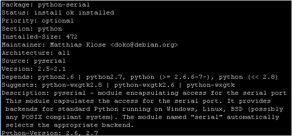 Now, if it is not installed, write the following command:
sudo apt-get install python-serial
After duly installing we are ready to connect our setup of chipKIT Digilent uC32 board and Basic I/O shield with USB to mini-B cable to Raspberry Pi! But, do not connect yet!
c) Connect chipKIT Digilent uC32 with BASIC I/O shield to Raspberry Pi
On Terminal of Raspberry Pi write:
lsusb
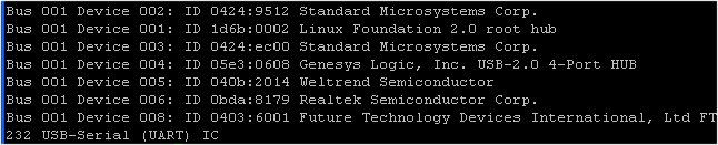
You will get a response similar to following:
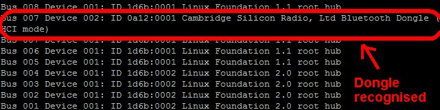
 I have an USB hub. where all my USB connections are made. I also have installed a TP-Link wireless dongle.
Now connect chipKIT Digilent uC32 board to Raspberry Pi board with USB cable.
On Terminal write again:
lsusb
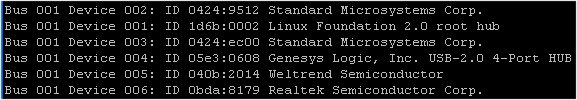
And the response now will be:
 Our chipKIT Digilent uC32 is recognized as having a FTDI serial IC.
We can check a bit more with the following command:
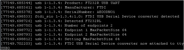
dmesg | tail
The response will be similar to following:
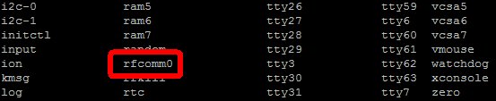
 The last bit is what interests us. We have identified our recent connection as ttyUSB0 (it can be 1 or 2 or whatever is your setup). We will use this information for next part of our Procedure.
Before anything else we will install Minicom if you have not already installed. You can read in b) how to check if it is installed with following command:
dpkg -s minicom
If it is not indtalled, write the following command:
sudo apt-get install minicom
After installation run the following command:
minicom -b 9600 -o -D /dev/ttyUSB0
If all is well with your setup you will see the following on Terminal:
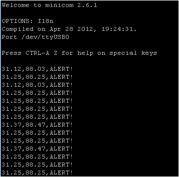 Alert is shown because we have this feature enabled and our temperature is over 24ºC threshold defined in our chipKIT Digilent uC32 firmware.
d) Install Telegram in Raspberry Pi
The starting point of installing Telegram is the vysheng github project which contains also installation instructions.
First we install packages needed to build telegram by typing on Terminal:
sudo apt-get install libreadline-dev libconfig-dev libssl-dev lua5.2 liblua5.2-dev libevent-dev make
Next, we clone Telegram CLI from github, making sure we are in /home/pi directory:
git clone --recursive https://github.com/vysheng/tg.git && cd tg
The recursive call is because two sub-projects tgl and tl-parser are also required. The && cd tg means that you end up in the tg directory ready for the next phase.
Before doing anything else we will make sure you we have enough /tmp for the compilation, by enlarging /tmp.
We need more space due to the fact that gcc places the intermediate compilation result (i.e. the expanded asm code + macros) in /tmp before linking takes place. Compilation fails if /tmp is too small. We will increase it 100MB. So edit /etc/fstab with:
sudo nano /etc/fstab
Add the following:
tmpfs /tmp tmpfs defaults,noatime,mode=1777,size=100m 0 0
The “size=100m” and similar other parameters force the RAM size used for the corresponding temporary file to certain megabytes. The “m” suffix corresponds to “mega bytes”.
Save and reboot
Make sure you are in /home/pi/tg directory. We make a build directory in order not to clutter the source code with intermediate object files.
mkdir build && cd build
Now we carry out the compilation there inside /home/pi/tg/build
../configure
Next we will compile
make
Compilation takes a while, but eventually you will be greeted hopefully with a successful installation.
e) Setting up Telegram
Telegram is based on (free) accounts associating a user name and a mobile phone number. In order to set things up you really need access to TWO phone numbers, although thereafter you only need ONE mobile phone to use it.
It is advisable to set up the Raspberry Pi to use the other mobile phone number that you will not be using. This second phone is only really needed to authenticate the account.
I actually did all the set up in Raspberry Pi.
Initially we can test telegram from the inside the folder /home/pi/build/bin. We will move later the binary files elsewhere so that they are easier to access and use.
First type the command inside /home/pi/tg/build/bin
./telegram-cli -k tg-server.pub -W
You should see some information printed about telegram, ending with a > prompt on the screen.
Press the “Enter” key a couple of times, and wait.
You should then see a prompt phone number:
Type in the phone number of a phone you have just set up, including the country code. eg
 +351912345678
Note, we will need access to the mobile phone in order to get a 5 digits authentication code.
We should then see the response:
code (‘call’ for phone call):
After a pause, we should get a SMS on the mobile phone we have just registered containing a 5 digits code number. Alternatively if you don’t receive the code it can ring you 2 minutes later and give you the code with an automatic voice.
Type this number into the Pi terminal and press “Enter”, to authenticate it.
We have set up Telegram in Raspberry Pi. The following image shows steps taken in my case /I have blured relevant information for basic security reasons):

Now we need to install Telegram in our own phone. I have installed “Unofficial IM App for Telegram” in my BlackBerry BB10 from Blackberry World. Apple Store and Google Play have official Telegram apps that you can download and install in your phone.
The first time we start Telegram in our phone we must enter the phone number, including land code (for example Portugal is +351).
Justas before we should receive on our phone a SMS message with a 5 digits code. Write the code and press “Enter”
Now we are ready to use telegram. In Raspberry Pi’s > pronpt write:
msg <Name_Lastname> testing message from Raspberry
Substitute <Name_Lastname> with the names you have just registered not forgetting that you need to use _ underscore between the first and last name.
You should get a message in your phone’s Telegram app. You can add the phone number you have used to register Telegram in your Raspberry Pi and then test sending a message.
The Terminal of your Raspberry Pi as well as your phone’s App will show the messages.
e) Write a Python program for Telegram
We will now write a Python program for reading from USB port, and accepting commands from Telegram.
Before we do anything else we need to install Pexpect which is found in The Python Package Index or better knows as PyPi, which is a repository of Python programs. Hence we will need to install it write in Raspberry Pi’s Terminal:
sudo apt-get install python-pip
After that, we will download Pexpect from the repository writing:
pip install pexpect
And that is it.
Now in /home/pi/tg/build/bin directory of your Raspberry Pi, write the following code, and name it tempmon.py. You can use the default nano editor.
#!usr/bin/env
#tempmon.py

import pexpect
import serial

ser = serial.Serial("/dev/ttyUSB0", 9600, timeout=2)

contact = "<Name_Lastname>" # substitute with registered name
telegram = pexpect.spawn('./telegram-cli -k tg-server.pub')

while True:
 ser.flush()
 data = ser.readline()
 telegram.expect('status', timeout=None)
 if (data != ""):
     data = ser.readline()
     processed_data = data.split(',')
     Data1 = str(processed_data[0])
     Data2 = str(processed_data[1])
     Data3 = str(processed_data[2])
     telegram.sendline('msg '+contact+' '+Data1+' '+Data3)
     print ('Message sent to '+ contact)
     telegram.sendline('quit')
Now run this code saved as tempmon.py
python /home/pi/tg/build/bin/tempmon.py
You will see the program waiting for a message from Telegram. Write “status” in your Telegram app. Immediate shortly you will see a message on Raspberry Pi’s Terminal:
Message sent to <Name_Lastname>
In your phone’s Telegram app you will see 26.0 OK or whatever temperature is read in ºC and if it is OK or there’s an ALERT.
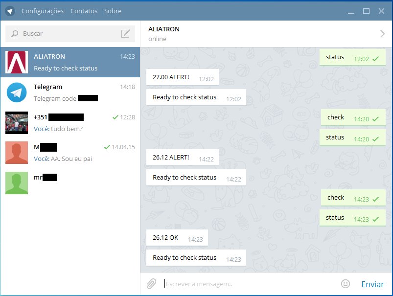
The following image shows Telegram working from PC’s desktop using the same phone number (Telegram functions in multiple devices):
 NOTE: I am enabling ALERT with rightmost switch on Basic I/O shield in top position.
f) Write a Lua script for Telegram
We will modify test.lua script.
Before writing anything, there were two further packages which needed to be installed on the Raspberry Pi. Write:
sudo apt-get install lua-lgi libnotify-dev
After installing you can try using the test.lua script
Once /home/pi/tg/build/bin directory type in:
./telegram-cli -k tg-server.pub -s test.lua
This should start Telegram with the line before the prompt saying:
Hi, this is lua script
We can try a couple of the procedures already built into it.
From your phone’s Telegram app send the message ping to your Raspberry Pi.
You Raspberry Pi should respond with the reply pong
Next send the message PING (all caps) to your Raspberry Pi. This time Raspberry Pi will respond with:
Forwarded from Your Name
PING
First we will copy action.lua script in order to keep it intact for any references, or changes:
cp action.lua tempmon.lua
Now let us edit tempmon.lua with:
sudo nano tempmon.lua
We will add a path variable to the beginning of the file, so that it will be easy to use telegram and the extra python scripts we will develop from any defined location. Immediately after the first two lines which set the variables started and our_id we will insert a line:
path = os.getenv("HOME")..'/tg/build/bin'
After function on_msg_receive (msg) find:
do_notify (get_title (msg.from, msg.to), msg.text)
Next to this add the following code:
if (msg.text == 'check') then
if (msg.to.id == our_id) then
os.execute('python '..path..'/tempmon.py')
send_msg (msg.from.print_name, 'Ready to check status', ok_cb, false)
else
send_msg (msg.to.print_name, 'Ready to check...', ok_cb, false)
end
return
end


Save <strong>tempmon.lua</strong> and we are now ready to test our set up.

<strong>g) Testing the set up for Remote Control</strong>

Run <strong>tempmon.lu</strong>a script by writing the following:

 ./telegram-cli -k tg-server.pub -s tempmon.lua
In your phone's Telegram app write: check
Next write: status
Raspberry Pi will reply with temperature and if everything is OK or there is an Alert!
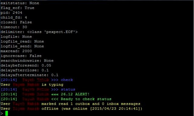
The Raspberry Pi's Terminal will show a prompt and the dumping of Python program when closing:
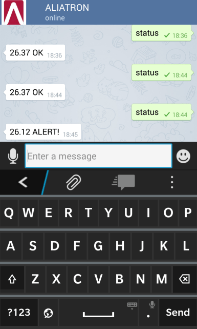
The following image shows the Telegram app the sending of commands and messages that have been received in my phone:
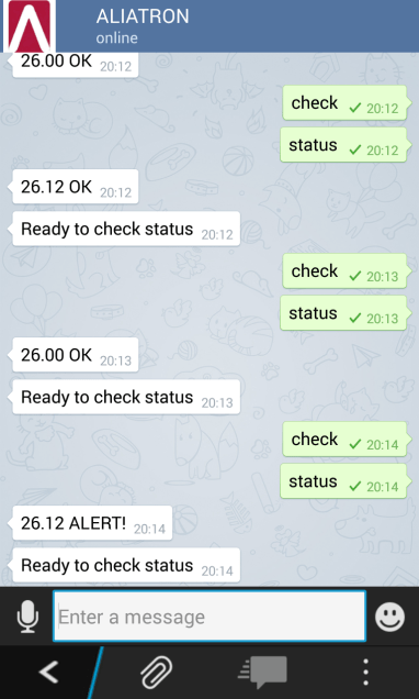
ALERT is enabled by putting in UP position the righmost switch on Basic I/O shield.
The following image shows the whole set up on a desktop at my company Aliatron:

What next?
In fact imagination and resources are the limit. We can add a camera that will send us snapshots of our control process, we can control equipment and devices and receive feedback from them, and much more.
In fact IM (Instant Message) apps such as Telegram can add a whole new dimension to Automation, provided security issues are addressed.
Acknowledgements
A special thank you is due to Robin Newman for his excellent tutorial at https://rbnrpi.wordpress.com. Everything Robin Newman wrote worked, and his post was an inspiration for this one I have just written.
A thank you is also due to Geeky Theory and their execellent website for the tutorial of Pexpect.
I had difficulties in compiling Lua, and could only sort it out after increasing the size of /tmp directory. A special thank you is due to Darmawan Salihun for his simple explanations.
Conclusions
Connecting up Raspberry Pi with a board such as chipKIT Digilent uC32 opens up a whole new range of interesting electronic projects. Microchip has already made it easy with chipKIT Pi, as mentioned at the beginning of this tutorial. Raspberry Pi offers lots of interesting and powerful solutions at low price, that can be combined with another low-priced board yet equally interesting and powerful chipKIT Digilent uC32. Digilent Basic I/O shield, that also offers more interesting electronic projects and proof of concept, with very same idea of connecting up with Raspberry Pi.


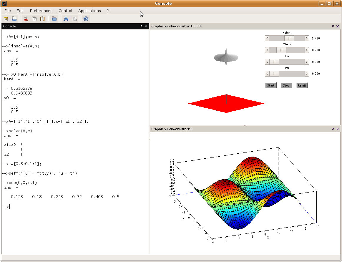


 3) Read temperture and plot with Scilab


 The plot shows variation of temperature by blowing air with mouth, over the processor. If we click onto “Stop measuring“, Scilab will stop reading the temperature and the plot will stop.


