Introduction
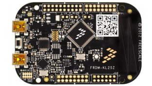
The Freescale FRDM-KL25Z board is an ultra-low-cost development platform for Kinetis L Series KL1x (KL14/15) and KL2x (KL24/25) MCUs built on ARM® Cortex™-M0+ processor. Features include easy access to MCU I/O, battery-ready, low-power operation, a standard-based form factor with expansion board options and a built-in debug interface for flash programming and run-control. The FRDM-KL25Z is supported by a range of Freescale and third-party development software, including mbed platform.
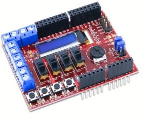
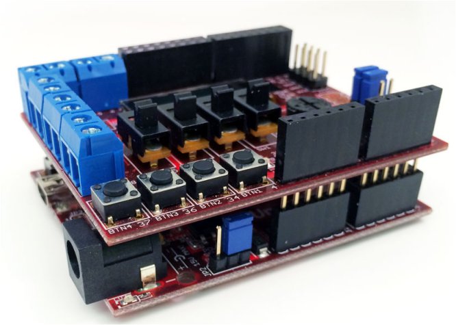
The Digilent Basic I/O shield is an input/output expansion board designed for use with chipKIT microcontroller boards such as the Uno32™ and the Max32™.
The Basic I/O Shield provides simple digital input devices such as switches and buttons, and digital output devices such as discrete LEDs and high current open FET drivers. It provides more advanced devices such as an I2C EEPROM, an I2C temperature sensor, and organic LED graphic display. A potentiometer is also provided for use as an analog input device. The Basic I/O Shield is designed to the same form factor as the Uno32 board, but is also usable with the FRDM-KL25Z board.
Remote viewing is an interesting proposition that we will dwell upon here with these two boards, and some extra material, such as a Bluetooth module and, at the end, Bluetooth-enabled phones.
Pre-Requirements:
You must have already done:
- Installation in Windows of your FRDM-KL25Z board.
- Tested FRDM-KL25Z with simple exercise such as blinking the RGB LED on it
If you done neither of the two above exercises, you ought to follow the introduction“Getting Started with mbed and Freescale FRDM-KL25Z board”.
Also you must have done temperature measurement with temperatur sensor TCN75A on Digilent Basic I/O shield.
Necessary material
You need the following boards:
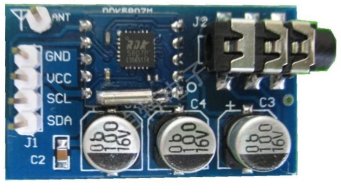
And Bluetooth adapter, Buletooth module and power supply unit:


– Freescale FRDM-KL25Z board
– Digilent BASIC I/O shield
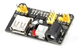
– Power supply unit (MB-102)for the set up
– Mobile Processing software
– Class I or II Bluetooth adapter
– JY-MCU Bluetooth Module (available from Aliatron)
Procedures:
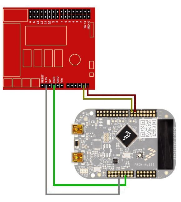
1 – Preparing our programming setup
The following connections will allow us to program the mbed board, and to prepare it

FRDM KL-25Z board is going to communicate with Microchip’s TCN75A temperature sensor on Digilent Basic I/O Shield.
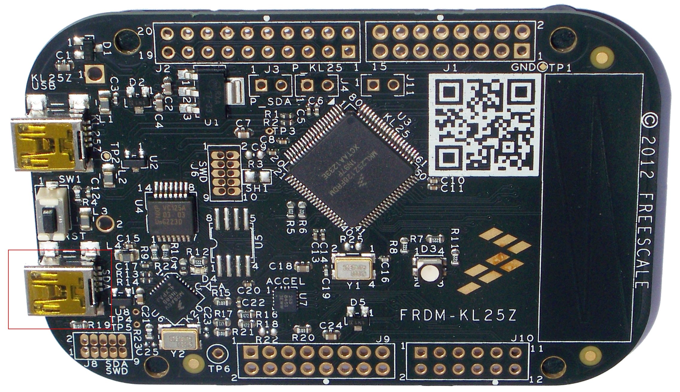
2. Connect your mbed-enabled FRDM-KL25Z to your PC
Use the USB lead to connect your FRDM-KL25Z to a PC, using the USB female connector labelled OpenSDA.
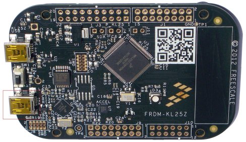
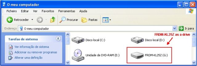
The status light will come on, indicating FRDM-KL25Z has power. After a few seconds of activity, your PC will recognise the mbed Microcontroller as a standard USB drive.
3. Visit the mbed website to get logged in, and to compile
The URL for mbed website is:
http://mbed.org
Log in with your normal username and password. This will give you access to the website, tools, libraries and documentation.
4. Open the mbed Compiler
Open the IOShield_Temp program and edit main.cpp (that you may have already written before)
Write the following code (just copy and paste):
int main() {
   char cmd[2];
   while (1) {
      cmd[0] = 0x01;
      cmd[1] = 0x00;
      i2c.write(addr, cmd, 2);

      cmd[0] = 0x00;
      i2c.write(addr, cmd, 1);
      i2c.read(addr, cmd, 2);

      float tmpC = (float((cmd[0]<<8)|cmd[1]) / 256.0);
      float tmpF = (float(9.0*tmpC)/5.0 + 32.0);
      // convert Centigrade into Fahrenheit
      pc.printf("%.2f", tmpC);
      pc.printf(",");
      // comma (,) separator necessary for string splitting
      pc.printf("%.2f", tmpF);
      pc.printf("");
      // somehow this extra line makes the reading more stable
      wait(0.5); // wait 0.5s
   }
}
Before anything else save your code.
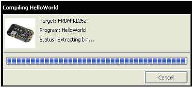
5. Compile and Download the Program
To compile the program, click the Compile button in the top toolbar.
 This will compile the program source code files within the program folder.

And a binary program will be created.
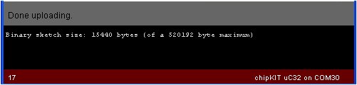
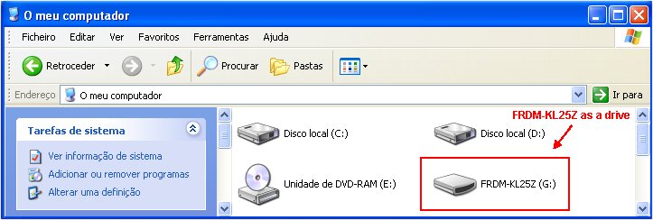
- After a successful compile, you will get a Success! message in the compiler output, and the download dialog will pop up to Save the binary program, or it will be automatically downloaded to your PC’s default Downloads folder. If you can Save, save it directly to FRDM-KL25Z board (acting as a drive), otherwise drag and drop, or cut and paste into your FRDM-KL25Z.
If everything goes well, FRDM-KL25Z is programmed. Power reset your FRDM-KL25Z.
6. Display the temperature on Terminal of PC
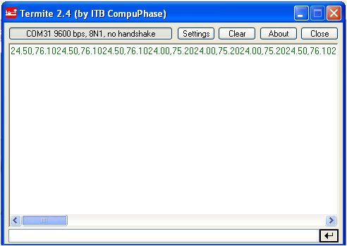
Launch a Terminal program such as Putty, or Termite. Ensure that the configuration settings of the port are Baud Rate 9600, Data bits 8, Stop bits 1, Parity none, Flow Controlnone. My port number is COM23 as can be seen (Termite’s port settings).
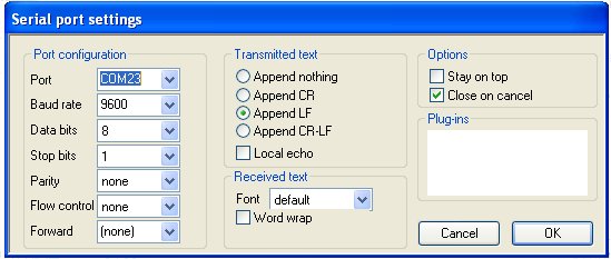
My FRDM-KL25Z board is connected to port 23. The port number can be seen at Device Manager of your Windows.
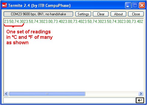
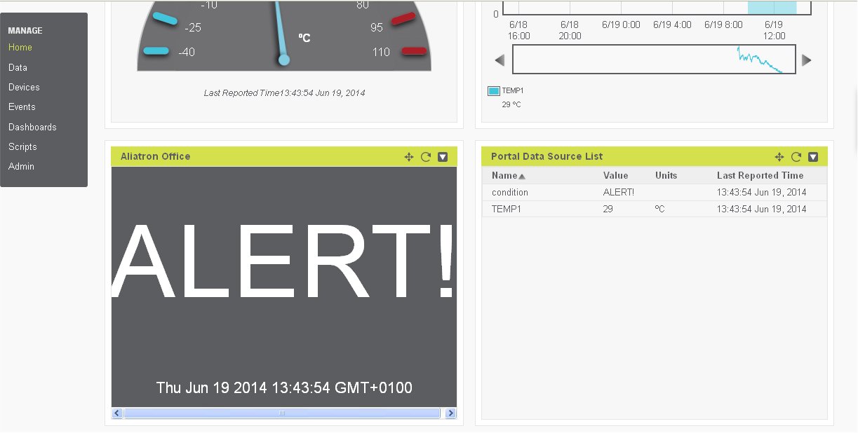
You will see immediately the temperature values being displayed:
We are now ready to add the Bluetooth connection.
7. Final setup
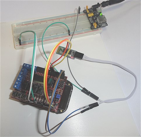
Connect up the boards, JY-MCU Bluetooth module, and power supply as shown:
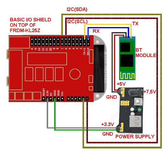
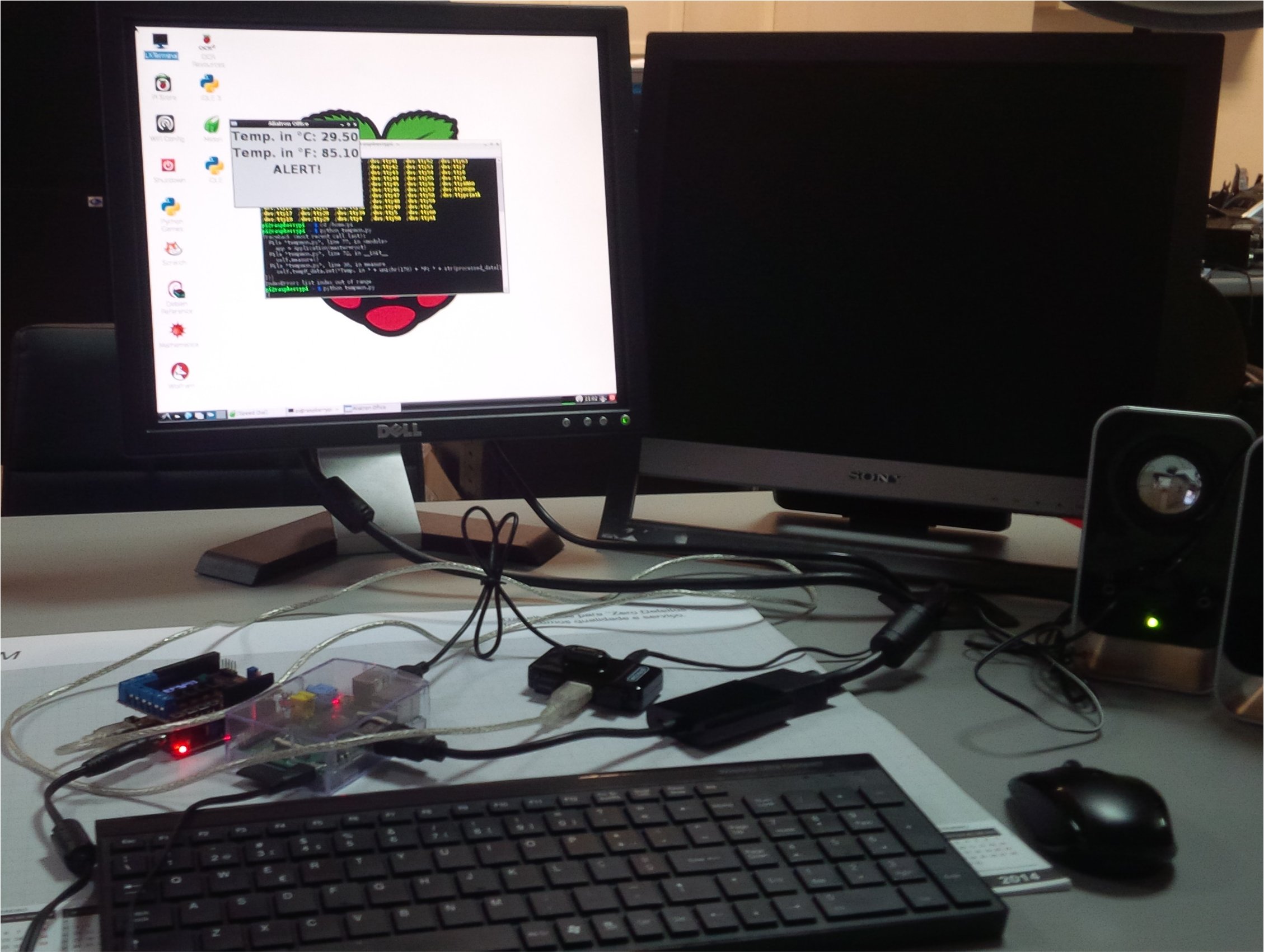
My actual set up looks like as the photo shows:

Note: the power supply and the way to connect the voltage supply is just my proposition. You can connect power supply in other ways.
Once the set up is powered you will see a blue LED blinking on your JY-MCU module.
Basic I/O shield must be installed on top of FRDM-KL25Z.
8 – Bluetooth installation in your PC
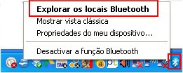
You must have your bluetooth adapter duly installed in your PC. My PC’s Bluetooth Sweex adapter shows in my sytem tray a bluetooth symbol. After activating bluetooth, I have the option to find the local bluetooth connections:
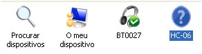
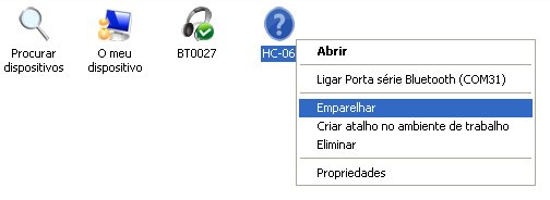
Do a search, and eventually you will find HC-06 (default name of JY-MCU module, a name that can be changed if required):
Next, we will connect to JY-MCU bluetooth module (found in my PC in COM31):

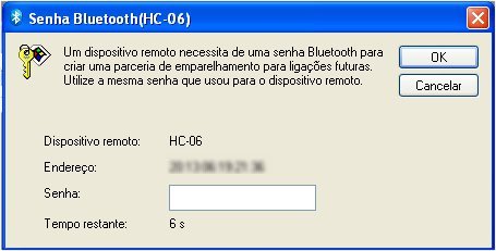
You will need to introduce the password which is ‘1234’:

I have blurred the MAC address of my bluetooth module. After introducing the password, click the OK button. You will see HC-06 connection as paired.

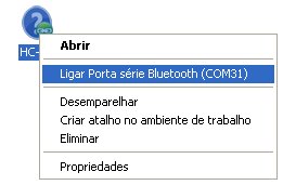
We next connect HC-06 to the serial port of your PC (in my case it is COM31):

The HC-06 icon will now change to green:

9) Display the temperature on Terminal of PC
We are ready to run the Terminal program. Ensure that the configuration settings of the port are Baud Rate 9600, Data bits 8, Stop bits 1, Parity none, Flow Control none. My port number is correct (in my case it is COM31). The result will be displayed as:
Having tested remote readings of temperature, we are now ready to write Apps for Bluetooth-enabled cellphones that will read the temperatures.
10) Display the temperatures on cellphones
The aim now is to display the temperature in a convenient way on:
– Android phone / tablet
– Blackberry phone
a) For Android, I have written code on MIT’s App Inventor Classic. The code is based on one written by kerimil at Instructables’ website.
I have modified kirimil’s code to read the incoming continuing string, and to split it into two variables, and made other minor adjustments, and given the project new name TempMon. It is beyond the aims of this tutorial to teach how to write code for App Inventor. There is ample teaching material on the Web, if you are interested.
So, if you want to write code, or modify, or even import, I have made it available on Bitbucket kept at Bitbucket, an unlimited free private repositories’ site. You can download the zip file, and upload to App Inventor Classic’s website. Click here to download the code.
The Android App, TempMonitor.apk, can be downloaded, if you do not want to write code. It is again available at at Bitbucket repository. Click here to download it.
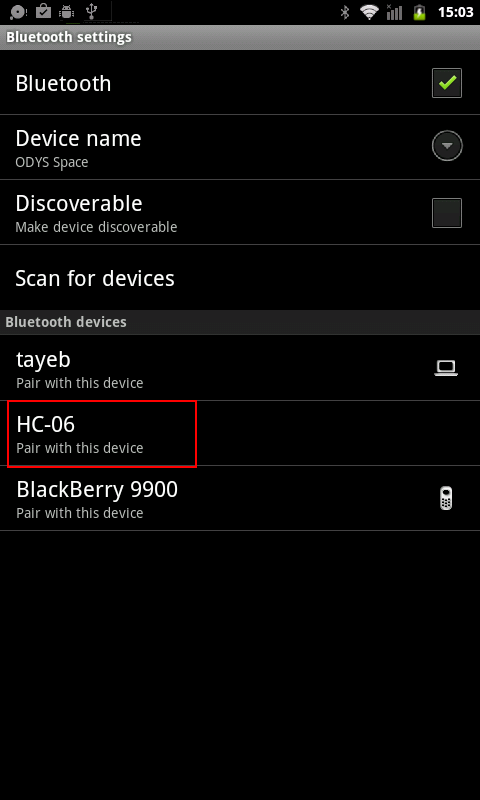
I assume you know how to upload, and to install an Android app. Once installed you will need to launch the App, but before that you need to enable Bluetooth in your Android phone, and to pair the JY-MCU module to your Android phone.

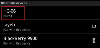
Next pair JY-MCU after searching for it, by pressing onto HC-06, and choosing to pair.
Introduce 1234 to pair, and click OK
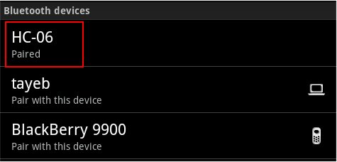
You will see that JY-MCU (named as HC-06) is paired:
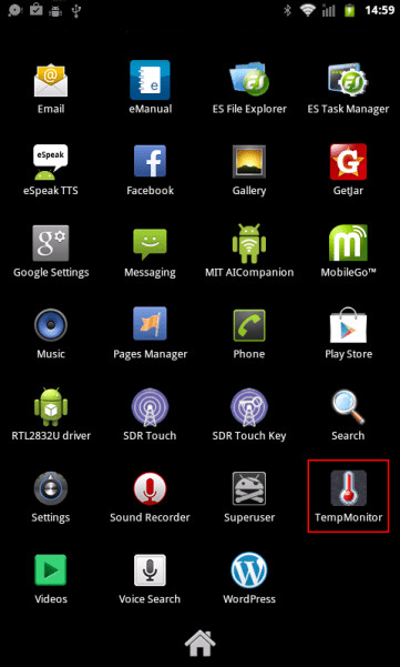
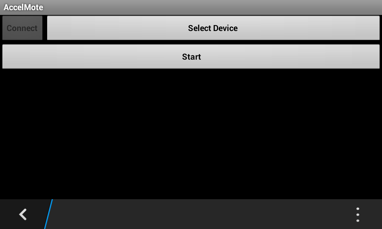
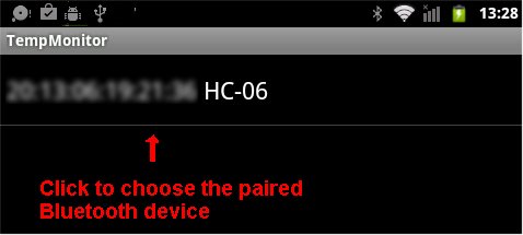
Now you are ready to launch the App which will be in your Android’s Apps folder:
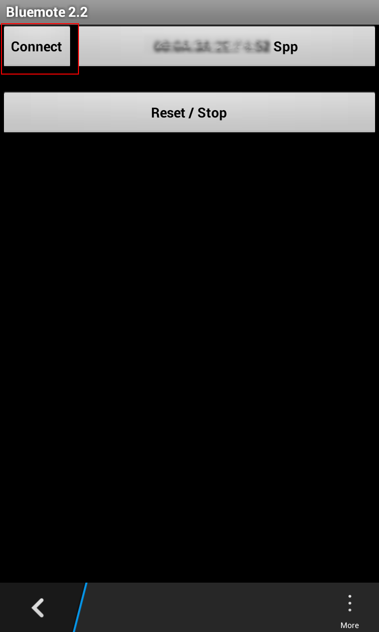
You will be greeted with following screen:
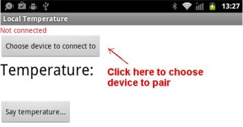
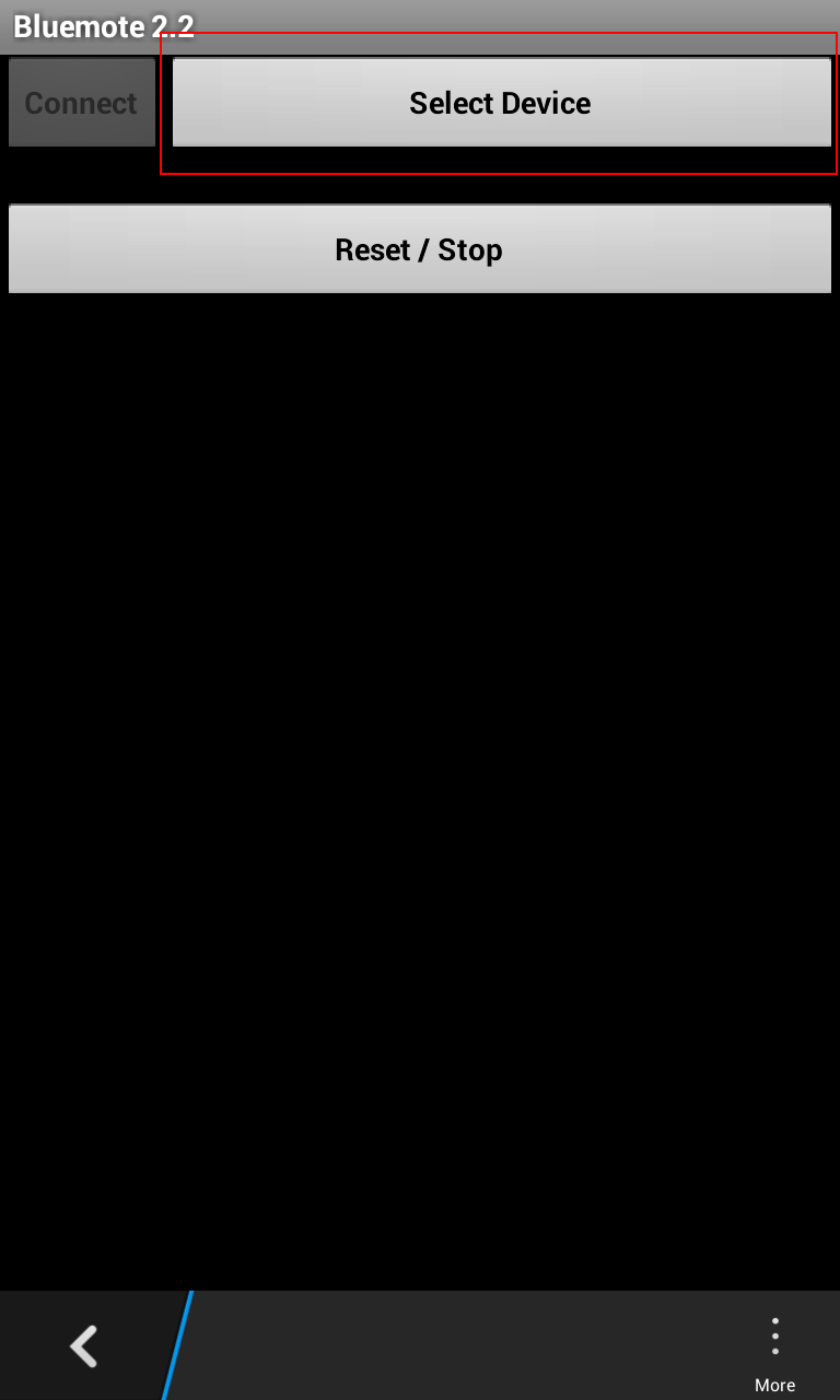
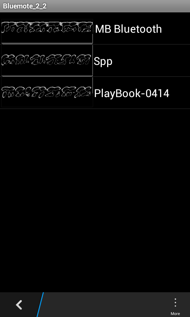
Click Choose device to connect to button, in next screen, click onto MAC address of your HC-06 (I have blurred the MAC Address of my device).
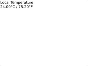
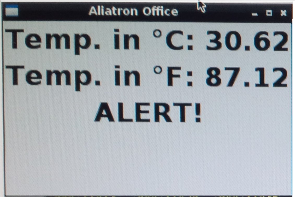
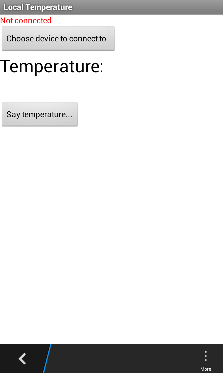
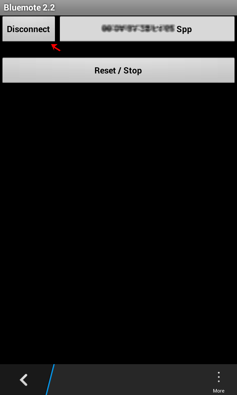
 On clicking, you will see the first screen on top and you will see that the device is connected, and the temperature will be displayed in ºC and ºF
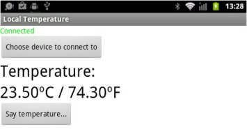
You can hear the temperature, by clicking Say temperature button.
b) For Blackberry (not BB10, but previous ones with Java OS – mine is Blackberry 9900) I have written code in Mobile Processing. f you do not know how to write Blackberry Apps in Mobile Processing, I suggest you follow my tutorial published here in this blog Write a Drawing App “myArtwork” for Blackberry with Social Networking Sharing Capability. You will need Mobile Processing, that you can download from Mobile Processing website.
You’ll also need a slightly patched Mobile Processing Bluetooth library:mobileprocessing-bluetooth-patched.zip. In the “libraries” directory of the Mobile Processing application, move the existing “bluetooth” library directory out of the way and unzip the above zipfile in its place.
The processing sketch is as follows:
import processing.bluetooth.*;
import processing.phone.*;
Bluetooth bt; //new bt device
Service[] services;
PFont font;
int state;
String msg;
String DEGREE = "\u00b0"; //to display correctly degrees symbol
Client c;
final int STATE_START = 0; //different states, similiar to events.
final int STATE_FIND = 1; //find devices
final int STATE_HOST = 2;
final int STATE_PLAY = 3; //once connected to device
byte[] inBuffer = new byte[11]; //store the bytes read from mBed in array.
//For the temperature sensor, there are only 11 digits
int counter;
void setup() {
font = loadFont();
textFont(font);
bt = new Bluetooth(this, Bluetooth.UUID_SERIALPORT);
counter = 1;
}
void draw() {
background(255);
if (state == STATE_START) {
fill(0);
textAlign(LEFT);
text("Welcome to mBed Bluetooth TempMon.\n\nFind device...\nPre ss any key", 2, 2, width - 4, height - 4);
}
else if (state == STATE_FIND) {
fill(0);
textAlign(LEFT);
if (services == null) {
text("Looking for SPP device...\n\n" + msg, 2, 2, width - 4, he ight - 4);
}
else {
String list = "SPP device found\n\n";
for (int i = 0, length = length(services); i < length; i++) {
list += i + ". " + services[i].device.address + "\n"; //this will list discovered devices
}
text(list, 2, 2, width - 4, height - 4);
}
}
else if (state == STATE_PLAY) {
c.readBytes(inBuffer); //Assigning assign the readBytes data into the inBuffer array for storing.
String inB2 = new String(inBuffer); //change the byte values into strings data int chars = inBuffer.length();
String[] dat = split(inB2, ','); // parse comma-separated number string into numbers
if (inBuffer != null) {
String data = dat[0] + DEGREE + "C / " + dat[1] + DEGREE + "F" ;
text("Local Temperature:\n" + data, 2, 2, width - 4, height - 4); //draw the message
}
text("Local Temperature:\n", 2, 2, width - 4, height - 4);
}
}
void libraryEvent(Object library, int event, Object data) {
if (library == bt) {
switch (event) {
case Bluetooth.EVENT_DISCOVER_DEVICE:
msg = "Found device at: " + ((Device) data).address + "...";
break;
case Bluetooth.EVENT_DISCOVER_DEVICE_COMPLETED:
msg = "Found " + length((Device[]) data) + " devices, looking for service...";
break;
case Bluetooth.EVENT_DISCOVER_SERVICE:
msg = "Found SPP service on " + ((Service[]) data)[0].device.address + "...";
break;
case Bluetooth.EVENT_DISCOVER_SERVICE_COMPLETED:
services = (Service[]) data;
msg = "Search complete.";
break;
case Bluetooth.EVENT_CLIENT_CONNECTED:
c = (Client) data;
state = STATE_PLAY;
break;
}
}
}
void keyPressed() {
if (state == STATE_START) {
//if any key is pressed.
services = null; // it will begin the search
bt.find(); //bt.find goes through the whole process of bluetooth searching
state = STATE_FIND;
msg = "Looking for devices...";
}
else if (state == STATE_FIND) { //this section will help connect to which device is found
if (services != null) {
if ((key >= '0') && (key &lt;= '9')) {
int i = key - '0';
if (i < length(services)) {
msg = "connecting...";
c = services[i].connect();
state = STATE_PLAY;
msg = "ready";
}
}
}
}
}
void destroy() {
bt.stop();
}
catch (java.io.IOException err)
{
}
catch (java.lang.SecurityException e)
{
}
catch (java.lang.IllegalArgumentException iae)
{
}
catch (IOException ioe)</pre>
{
}
You will now save the project with a name such as TempMon with File->Save As in the main dropdown menu.
Before proceeding, you will create an Icon for our App. It needs to be 62×62 pixels. You can download here an icon we have designed, together with pde file of above code. The file is hosted by Bitbucket. Bitbucket offers unlimited public and private repositories, and it is free for small teams. In your PC’s My Documents -> MobileProcessing ->TempMon folder paste data folder that includes icon image file icon.png and TempMon.pde sketch (Mobile Processing and other Processing codes are known as ‘sketches’).
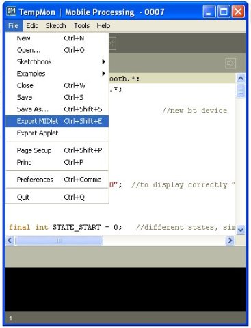
Export as MIDlet with File-> Export MIDlet:
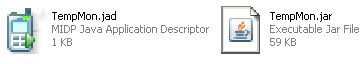
The MIDlet will be created and your PC´s My Documents -> MobileProcessing ->TempMon -> MIDlet folder (will open automatically to show TempMon.jad, TempMon.jar and My Documents -> MobileProcessing ->TempMon.java files:
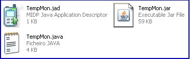
Note: If you care to check TempMon folder you will also see a new folder proguard.ProGuard is included in Mobile Processing to make the apps smaller, and more efficient jar files. We will not use the jad and jar files in this folder.
We are now ready to copy TempMon.jad and TempMon.jar into the Blackberry.
After connecting your Blackberry to your PC with USB cable, run Blackberry Desktop software and choose Files:
Click the Start button. You will see the next screen:
In your PCs folder MIDlet folder select TempMon.jad and TempMon.jar files:

And with right click of your mouse button Copy these files, and paste them into theBlackberry Desktop folder you have just opened:

Both files will be now in your Blackberry phone’s documents folder.
NOTE: If you are too lazy to write code you can install jad and jad files found here (after unzipping) into your Blackberry as shown. Note jad and jar files are hosted at Bitbucket, a free and unlimited public and private repositories hosting site.
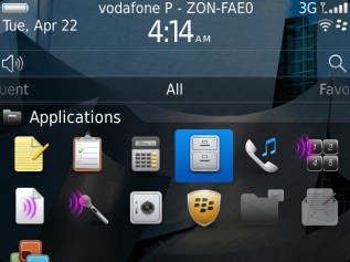
Now disconnect the USB cable between your Blackberry and your PC. In your Blackberry go to All group of folders, and choose Applications folder:

Open the folder, and select Files folder:
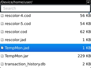
Open the Files folder and navigate to the documents folder. In my Blackberry, I found it in File Folders -> Device -> home -> user. In documents folder within user folder, you will find TempMon.jad and TempMon.jar . Select TempMon.jad and click on it:
You will see the next screen:
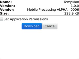
Click the Download button. Our app will start to be installed. You will get next a warning window that the application does not contain a signature, just click Yes and let the App be installed. If successful, you will be invited to immediately Run it.
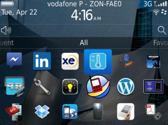
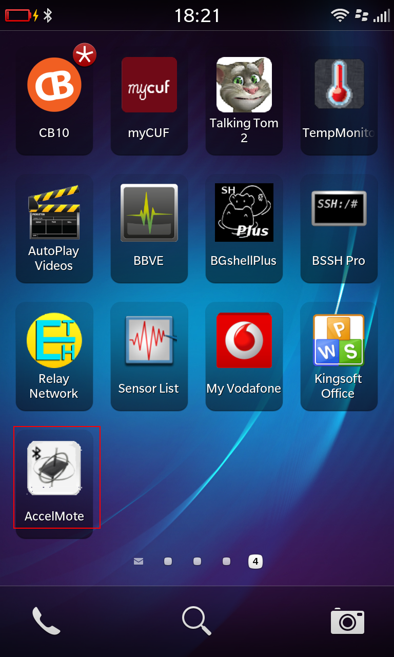
Once installed, the App’s icon will be as show below:
Make sure your Blackberry is paired to HC-06 (the name of JY-MCU Bluetooth module). The password is 1234.
Run the App, and if everything is alright you will see the following screen:
Conclusions
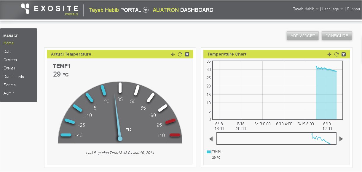
We have achieved remote temperature viewing of temperature read by our Freescale FRDM-KL25Z board from the temperature sensor Microchip TCN75A on Digilent Basic I/O shield.
We have used App Inventor Classic and Mobile Processing to read remotely temperature on two smartphones, respectively Android and Blackberry.
I shall appreciate any comments, and suggestions. I will also appreciate if you point out any errors or omissions in this tutorial.


 Take note of the location of your sketches (MPIDE codes are called “sketches”). In your Windows navigate to where the folder is, and create a directory named ‘Libraries’.
 So here we are to go to next procedure
 Install the Basic I/O shield on top of Uc32 as shown on the above image . Connect to the PC with USB cable. USB connection will power the Uc32 and the Basic I/O shield simultaneously. Connect the FM module to uC32 and Basic I/O shield.
 c) Firmware installation
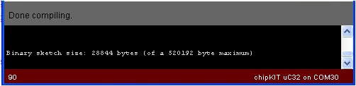 Now we are ready to upload the firmware.
 If all is well you can now tune FM Radio stations. The pot on Basic I/O is to be used to tune in the radio stations.


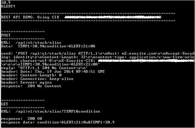
 Note that rightmost switch is toggled to up position. Only in this position the Alert for temperature above 24ºC will work.


