
Introduction
The chipKIT development platform with prototyping-friendly 32-bit MCU packages (based on PIC32 microcontrollers) from Microchip is an open-source hardware and software solution intended for beginners and users with little or no knowledge of embedded controllers wanting to explore embedded applications.
The chipKIT environment advances the art of open-source, physical computing by expanding support to more chip platforms and introducing new, high-performance libraries. It combines low-cost hardware with free software that is fast, powerful, and extendable. Inspired by Arduino™, chipKIT controller boards and software tools are easy to use by beginners of any age and specialists in any field. These boards and tools are compatible with the standards established for the hobbyist community and also offer a clear migration path to professional-grade tools for experienced engineers(1)
Most recently LabVIEW Interface for ChipKit has been made available. The LabVIEW Interface for ChipKit (LIFCK) Toolkit is a FREE download that allows users to acquire data from a ChipKit development platform and process it in the LabVIEW Graphical Programming environment. LabVIEW (short for Laboratory Virtual Instrument Engineering Workbench) is a system-design platform and development environment for a visual programming language from NI (National Instruments). The graphical language is named “G” (not to be confused with G-code). Originally released for the Apple Macintosh in 1986, LabVIEW is commonly used for data acquisition, instrument control, and industrial automation on a variety of platforms including Microsoft Windows, various versions of UNIX, Linux, and Mac OS X. The latest version of LabVIEW is LabVIEW 2013. (2)
Objectives
Install the required hardware and software to interface NI’s LabVIEW to Digilent’s chipKIT UNO32 board, and test an application that blinks a LED.

Requirements
– Digilent UNO 32 Development Board

– MPIDE software
– LabVIEW 2013 software
NOTE: If you do not own a copy of LabVIEW, you can download a non-commercial student license and request usage for 6 months.
A free, 45 day evaluation of LabVIEW is available at ni.com/trylabview. You are required to obtain a NI user profile to extend the 7-day evaluation to 45-days!
Procedure
1) chipKIT running on Windows
The fundamental steps to get chipKIT running on a PC are:
a) Download the MPIDE environment
The MPIDE programming software can be dowloaded from chipKIT’s website. It is a zipped file that you can unzip to a location on your hard drive say C:\chipkit. You will end up with following file structure:
![mpide-exe1-1024x571[1]](https://redacacia.me/wp-content/uploads/2013/08/mpide-exe1-1024x5711.png)
b) Connect UNO32 board
Connect the USB cable to one of the PC’s USB ports and then to the mini-A USB connector of UNO32. UNO32 can be powered via USB connection, or with an external power supply. The power source is selected automatically by sensing circuitry on the board. So for this set up we will not need external power supply as UNO32 will be powered from USB port of your PC.
c) Install the USB drivers
The installation procedure will depend on the OS of your PC. UNO32 use a FTDI USB interface chip. Your OS should detect the device once it is connected:

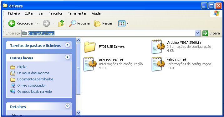
If you allow Windows to search online, it should locate the driver and install it properly. Nevertheless if you do not want to risk you can install the drivers from the folder of MPIDE. Within drivers sub-folder you will find FTDI USB Drivers:
Alternatively drivers can be downloaded here on FTDI’s website. Once the driver is installed check in Definitions -> Control Panel -> System -> Hardware -> Device Management -> Ports (COM and LPT) and check the port number of your USB connection. In my case it is port 21:

d) Run MPIDE
Now we are ready to run MPIDE programming environment. In your chipKIT folder you will find the MPIDE icon. Click the icon (in my Windows XP set up I have to start the program as Administrator, so you may have to do the same):

When it is launched you will see the following screen:

In Tools -> Board choose chipKIT UNO32:

Next again in Tools -> Serial Port choose the serial port where your USB connection is made (in my set up is port 21):

The codes for UNO32 are called sketches. The word “sketch” is inherited from Processing an open source programming language.
The Processing project was initiated in 2001 by Casey Reas and Benjamin Fry, both formerly of the Aesthetics and Computation Group at the MIT Media Lab. One of the stated aims of Processing is to act as a tool to get non-programmers started with programming, through the instant gratification of visual feedback. The language builds on the Java language, but uses a simplified syntax and graphics programming model.
Many example sketches are included with the MPIDE environment. We will blink a LED, so we will choose in File -> Sketchbook -> Examples -> Basics -> Blink:

As you will note the syntax is quite simple in MPIDE environment. If you are familiar Arduino Processing environment you will note they are the same.
e) Run the Blink sketch on UNO32
Click the “Upload” button in your MPIDE environment as shown:

If everything is OK, you will see that the sketch is uploaded into UNO32:

If it is successully uploaded in your MPIDE environment you will see “Done Uploading”:

And after few seconds you will see the green LED on your UNO32 blinking every one second.
You have successfully programmed UNO32! At this stage it is quite convenient, for learning purposes, to register yourself in ChipKIT forums, and to check around.
2) LabVIEW environment
This is your development environment where you will write your computer program to control the chipKIT device UNO32.
a) Install Labview 2013 and NI-VISA
Download and install LabVIEW 2013 if you do not have it already.
Next install NI-VISA device driver. This is a library of functions that enable LabVIEW to send and receive commands for various communication protocols such as RS-232 and IEEE488.2. VISA drivers are free for use and can be downloaded from ni.com/drivers.
If you have doubts, please check the NI website and follow instructions. Installing Labview and drivers is quite an easy process!
b) Install JKI’s VI Package Manager
JKI is a NI Alliance Partner (jist like my company Aliatron is) and is an integrator of NI solutions. The Package Manager will allow you to install the LabVIEW interface for chipKIT add-on with all functions, examples and help files. Download JKI’s VI Package Manager and install it by clicking on the JKI’s icon in your PC’s folder where you have downloaded it.
c) Install LabVIEW interface for chipKIT
This is an API (set of functions) that allow LabVIEW to control and communicate with the chipkit UNO32 board. It is a free tool that for download on the Labview interface for chipKIT community. Current release is 1.0.0.8. Click on the icon:

And JKI’s VI Package Manager will open inviting you to install the LabVIEW interface:
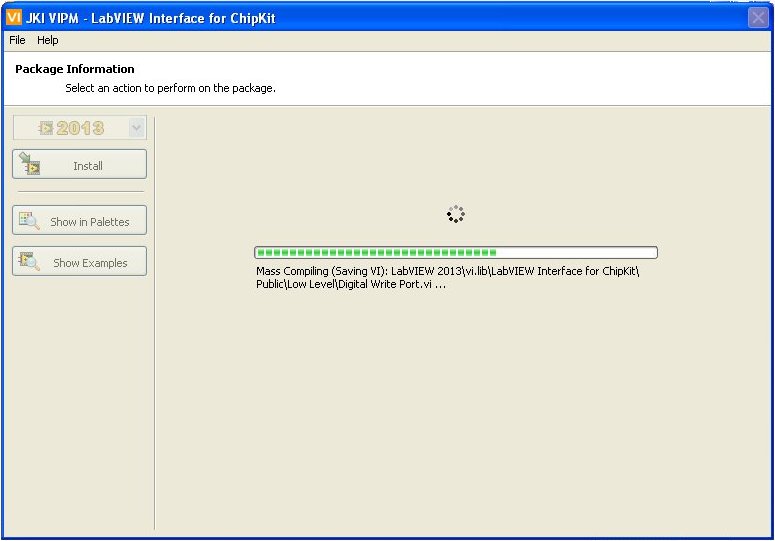
Once installed you will see the following re-assuring screen:

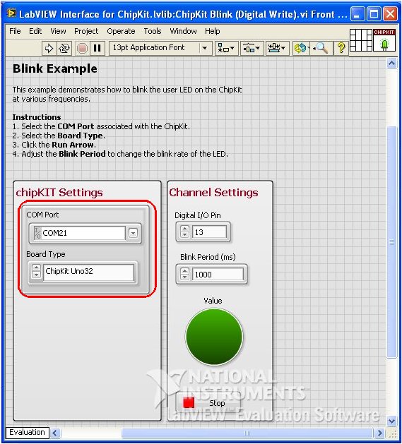
Click Show Examples button. And choose “chipKIT Blink (digital Write).vi” clicking on the icon.
Check if your UNO32 is connected to PC with USB cable.
LabVIEW will open with the launched VI. Change the chipKIT setting as shown in red box of the image:
Now Run the VI clicking the run botton ![]() . After few seconds an error will occur:
. After few seconds an error will occur:

As the pop up indicates our UNO32 has not the latest firmware. In fact it has no firmware to communicate with LabVIEW. The firmware is found in LabVIEW folder in vi.lib\LabVIEW Interface for Chipkit\Firmware\Chipkit.
d) Deploy LabVIEW interface for chipKIT firmware (LIFCK)
Launch MPIDE environment as before.
After doing File-> Open, navigate to C:\Program Files\National Instruments\LabVIEW2013\vi.lib\LabVIEW Interface for ChipKit\Firmware\ChipKit\LIFCK_uC32 and choose LIFCK_uC32.pde sketch as shown:

Note: You may need to teak again in Tools the Board and Serial Port number.
Once the fimware is loaded, click on Upload to board button ![]()
The firmware sketch will be uploaded to UNO32 board, and if everything goes well the result will be “Done uploading”:
The green LED on the board will now be permanently ON.
NOTE: The firmware for uC32 (another chipKIT board from Digilent) is same as for UNO32 board.
3) Run blinking VI in LabVIEW
Exit MPIDE environment, and launch LabVIEW 2013 again. Choose the VI as shown which should be now in LabVIEW screen:

Change the chipKIT setting as shown in red box of the image:
The port number will be the one found in your PC as shown earlier.
Now Run the VI clicking the run botton ![]() . After few seconds you will see the green LED on UNO32 blinking once every second.
. After few seconds you will see the green LED on UNO32 blinking once every second.
In Tools choose Block Diagram. This will show the graphic components of LabVIEW.
NOTE: You will see a set up of how to connect UNO32 board in LabVIEW’s Block Diagram of a breadboard plus resistor and LED. In fact for this tutorial purpose, you do not need to connect to external LED on a breadboard, as the green LED on UNO32 is connected to port 13 andl LabVIEW sends the digital command to port 13:

Digilent offers many connectivity solutions including a quite interesting board Basic I/O Shield for UNO32:

I/O shield on top of UNO32 board
Also, if you want to write the VI we have used, there is an excellent step by step tutorial at https://decibel.ni.com/content/docs/DOC-29229
Watch our uploaded video on Youtube, showing the Digilent UNO32 board being controlled by LabVIEW:
And also watch video showing Digilent UNO32 board and Basic I/O shield and blinking of LED on port 29:
Resources
1) NI Community: https://decibel.ni.com/content/groups/labview-interface-for-chipkit
2) Digilent UNO32: http://www.digilentinc.com/Products/Detail.cfm?Prod=CHIPKIT-UNO32
3) Digilent Basic I/O Shield: http://www.digilentinc.com/Products/Detail.cfm?NavPath=2,719,935&Prod=CHIPKIT-BASIC-IO-SHIELD
Conclusions
We have shown how to interface LabVIEW to chipKIT Digilent UNO32 development board. This solution of interfacing LabVIEW offers enormous potentiaties for projects. Though we did very little extra work (we based on already existing work), the idea behind this tutorial is to show how easy it is for LabVIEW to communicate with chipKIT devices. Check here in this blog other tutorials for LabVIEW that may interest you.

Pingback: LabVIEW and VISA interface, with chipKIT Digilent UNO32 and Basic I/O Shield | RedAcacia
Pingback: Remote Viewing with NI LabVIEW, Digilent UNO32 and Basic I/O Shield | RedAcacia
Pingback: Using the Chrome Serial API with chipKIT Digilent UNO32 | RedAcacia
Q: Can I deploy code to the chipKIT device from LabVIEW and disconnect the USB so that it can run autonomously?
A: The LabVIEW Interface for ChipKit allows users to interface with the ChipKit and requires a constant connection (via USB) between the ChipKit and LabVIEW running on the host computer. The goal of the LabVIEW Interface for ChipKit is to enable users to interact with the ChipKit while taking advantage of the processing power of the PC and signal processing and user interface power of LabVIEW. It is currently not possible to run LabVIEW code on the ChipKit autonomously.
Welcome to my blog. Thank you for your intervention in case someone does not understand the purpose of connecting Labview and chipKIT. I have also shown here remote connecting without USB cable with recourse to bluetooth module.
hello, i’m trying to do a blink led, but with the led 5 (pin 43), but it doesn’t work, could you help, me?
Welcome Leonardo to my blog. Does the example work for other pins with your set up?
Yes, it’s works fine, but for this pin(43) doesn’t work.
Hello Tayeb. I am student of electronics engineering in Colombia. I am making a student project. It’s a data acquisition system. My partners and I had thought a solution based on Arduino Mega+Labview but we have a big problem. One of the requirements for the project is the sample rate. We need at least 10kHz and this was not possible with Arduino Mega+Labview. Reading some forums I found Chipkit Max32 and now I read your blog and I see the development for ChipKit Max32+LabView is similar to Arduino+LabView. My question is: Can I get a sample rate of al least 10kHz with ChipKit Max32+LabView?
Arduino Mega card has this sample rate but using with LabView this reduces.
Welcome to my blog. Sorry it took me so long to reply. I have abroad without Internet access. I am not sure about Labview reading so fast. Surely with NI cards you can achieve fast rates of acquisition.
Hi Tayeb Thanks for your tutorial. Just for information, do you know than Labview Hackers have create a new toolkit for Arduino/ChipKit. You can fin it hear: http://sine.ni.com/nips/cds/view/p/lang/fr/nid/212478
Best regards from France
Eric Bobillier
Merci Eric.
And welcome to my blog. Will follow your link.
Pingback: LabVIEW: LINX and chipKIT » chipKIT Development Platform