
Introduction
chipKIT Digilent uC32 (or Uno32) and Raspberry Pi are both pretty cheap, almost of the same size, and although they look similar, they are different. The Raspberry Pi is effectively a mini-computer, running a Linux operating system (OS), and the chipKIT is a microcontroller, without a typical typical OS, but purpose-built with important features such as EEPROM, analog inputs and PWM outputs, features that Raspberry Pi does not have. On other hand, Raspberry Pi offers Ethernet connection, USB Master, video and audio outputs, all of these that are not available on chipKIT, can enhance any electronic project.
There is already a marriage between chipKIT and Raspberry Pi, called chipKIT Pi that makes it easy to connect Raspberry Pi to chipIT. The chipKIT Pi board fits nicely on the Raspberry Pi interfacing directly on the IO header of the Raspberry Pi. The board can be used without Raspberry Pi, in stand-alone mode and for this reason there is a DC plug, useful to power the board with a power supply. The ICSP header (JP3) has been added to program the on-board microcontroller PIC32MX250F128B using a Microchip PICkit or a ICD in-circuit debugger/programmer.
Objectives
- Capture the local temperature with Microchip TCN75A temperature sensor on Digilent Basic I/O shield using chipKIT Digilent uC32 board
- Make the reading available through USB port to Raspberry Pi
- Make Raspberry Pi with a Python program to read from the USB port, and display the values of temperatures as read from USB port.
Setup
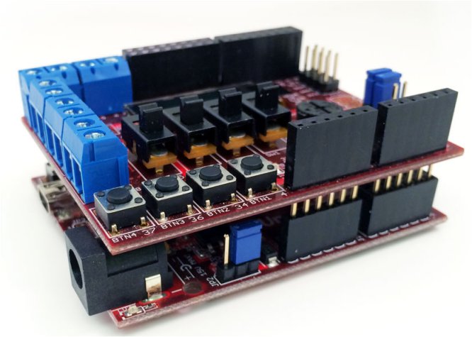
- chipKIT Digilent uC32 with Digilent Basic I/O shield on top, and power supply
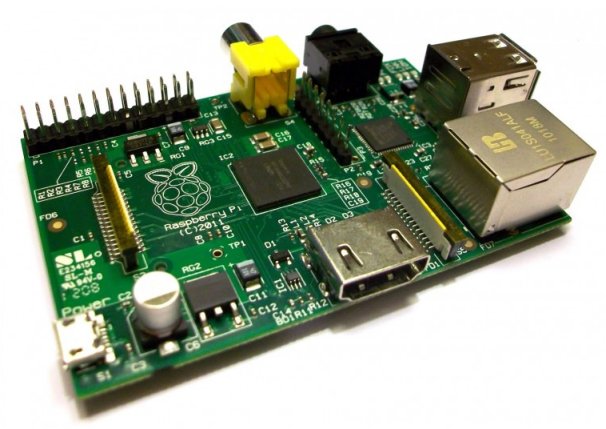
- Raspberry Pi Model B and power supply (and I recommend a powered USB hub)
- USB A to mini-B cable
 Procedure
a) Install libraries of Basic I/O Shield in MPIDE environment for uC32 board
On uC32 you must have Jumpers JP6 and JP8 set in the RG3 and RG2 positions. Install the Basic I/O shield on top of UNO32 as shown on the above image . Connect to the PC with USB cable. Although USB connection will power uC32 and the Basic I/O shield simultaneously, we will use external power supply to uC32 board.
We assume that you have already installed MPIDE environment.
You will need to know the location of MPIDE sketches folder:
Run MPIDE ![]() . In menu do File -> Preferences find the sketchbook location:
. In menu do File -> Preferences find the sketchbook location:
 Take note of the location of your sketches (MPIDE codes are called “sketches”). In your Windows navigate to where the folder is, and create a directory named ‘Libraries’.
Download from here the zipped file containing libraries and documentation for using the Basic I/O Shield™ with the chipKIT MPIDE and unzip into the Libraries folder you have just created:
 Now if you do File -> Examples you will see three folders IOShieldEEPROM, IOShieldOled and IOShieldTemp. Open the sketch IOShieldTemp_Demo:

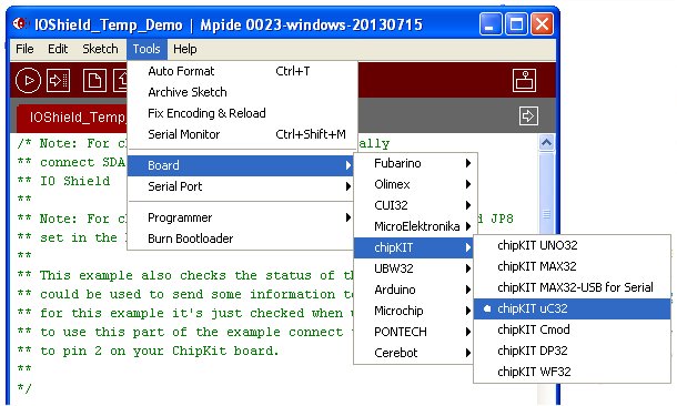
Next choose the board (in our case chipKIT uC32):
 And choose Serial Port to which the board is connected in Tools >> Serial Port >> (port where UC32 is connected). In my case it is COM30.
Now we are ready to upload the sketch to the board. Click the Upload button ![]() on MPIDE environment.
on MPIDE environment.
If successful you will see the following results at bottom of MPIDE environment:
 We are now ready to check what is being sent to our COM30 port (your PC’s may be other) in Tools >> Serial Monitor.
A new window will pop up showing the readings sent to your PC’s serial port: We are getting readings in degrees C and degrees F. Note that Alarm is not displayed even though the temperature is above 24ºC as set in our sketch (you can check – it is clearly written). This happens because in uC32 and Uno32 boards you need to toggle to top the rightmost switch on Basic I/O shield If you do so, ALERT will sent to serial port. You can use the switch to switch off the Alarm by toggling down the switch.
If you are here, the rest will go smoothly.
We will now change this sketch, and adapt it to Raspberry Pi to be read easily by Python. Also ,we will add code to show the temperature on OLED display of Basic I/O shield.
/* Original source code at
http://chipkit.net/tag/temperature-sensor/
Modified and adapted by Tayeb Habib tayeb.habib@gmail.com
http://redacacia.me
*/

#include <IOShieldTemp.h>
#include <IOShieldOled.h>
#include <Wire.h>
#define ALERT_PIN 2

int tensc = 0;
int onesc = 0;
int dot_tensc = 0;
int dot_onesc = 0;
int tensf = 0;
int onesf = 0;
int dot_tensf = 0;
int dot_onesf = 0;
int tempC=0;
int tempF=0;

void setup()
{
  Serial.begin(9600);
  pinMode(ALERT_PIN, INPUT);
  //set up the OLED display
  IOShieldOled.begin();
  IOShieldOled.setCharUpdate(0);
  IOShieldOled.displayOn();
  IOShieldTemp.config(IOSHIELDTEMP_ONESHOT | IOSHIELDTEMP_RES11 | IOSHIELDTEMP_ALERTHIGH);
  //Set the range to bring the alert pin high if it's above 78F (25.5C), alert will stay
  //high until the temp drops below 75.2F (24C).
  IOShieldTemp.setTempLimit(IOShieldTemp.convFtoC(78)); // 78.0F ~ 25.5C
  IOShieldTemp.setTempHyst(24); // 75.2F ~ 24.0C

}
void loop()
{
  float tempf, tempc;
  //Get Temperature in Celsius.
  tempc = IOShieldTemp.getTemp();

  // Convert the result to Fahrenheit.
  tempf = IOShieldTemp.convCtoF(tempc);

  //Print Temperature to serial port
  Serial.print(tempc);
  Serial.print(",");
  Serial.print(tempf);
  Serial.print(",");
  if(digitalRead(ALERT_PIN) == HIGH)
    Serial.print("ALERT!");
  else
    Serial.print("OK");
  Serial.print("\r\n");

  //parse data for temperature in celcius
  tempC=tempc*100;
  dot_onesc = tempC%10;
  tempC = tempC/10;
  dot_tensc = tempC%10;
  tempC = tempC/10;
  onesc = tempC%10;
  tempC = tempC/10;
  tensc = tempC%10;

  //convert data to ASCII for temperature in celcius
   tensc = tensc+48;
   onesc = onesc+48;
   dot_tensc = dot_tensc+48;
   dot_onesc = dot_onesc+48;

  //parse data for temperature in Fahrenheit
  tempF=tempf*100;
  dot_onesf = tempF%10;
  tempF = tempF/10;
  dot_tensf = tempF%10;
  tempF = tempF/10;
  onesf = tempF%10;
  tempF = tempF/10;
  tensf = tempF%10;

  //convert data to ASCII for temperature in Fahrenheit
   tensf = tensf+48;
   onesf = onesf+48;
   dot_tensf = dot_tensf+48;
   dot_onesf = dot_onesf+48;

  //Clear the virtual buffer
  IOShieldOled.clearBuffer();

  //Draw a rectangle over wrting then slide the rectagle
  //down slowly displaying all writing
    IOShieldOled.clearBuffer();
    IOShieldOled.setCursor(0, 0);
    IOShieldOled.putString("Aliatron Office");
    IOShieldOled.setCursor(0, 1);
    IOShieldOled.putChar(tensc);
    IOShieldOled.setCursor(1, 1);
    IOShieldOled.putChar(onesc);
    IOShieldOled.setCursor(2, 1);
    IOShieldOled.putString(".");
    IOShieldOled.setCursor(3, 1);
    IOShieldOled.putChar(dot_tensc);
    IOShieldOled.setCursor(4, 1);
    IOShieldOled.putChar(dot_onesc);
    IOShieldOled.setCursor(6, 1);
    IOShieldOled.putString(" Degrees C");
    IOShieldOled.setCursor(0, 2);
    IOShieldOled.putChar(tensf);
    IOShieldOled.setCursor(1, 2);
    IOShieldOled.putChar(onesf);
    IOShieldOled.setCursor(2, 2);
    IOShieldOled.putString(".");
    IOShieldOled.setCursor(3, 2);
    IOShieldOled.putChar(dot_tensf);
    IOShieldOled.setCursor(4, 2);
    IOShieldOled.putChar(dot_onesf);
    IOShieldOled.setCursor(6, 2);
    IOShieldOled.putString(" Degrees F");
    IOShieldOled.setCursor(0, 3);
    if(digitalRead(ALERT_PIN) == HIGH)
       IOShieldOled.putString("A L E R T !");
    IOShieldOled.updateDisplay();
  delay(1000);
}
The OLED display on BASIC I/O shield will show something similar to following image:
 Note that rightmost switch is toggled to up position. Only in this position the Alert for temperature above 24ºC will work.
Now we are ready for Raspberry Pi!
b) Preparing Raspberry Pi
As a requirement your Raspberry Pi must have an already working Raspbian OS, and mouse and keyboard duly configured, and with network connection to Internet duly installed. If not, you need to do all those things before proceeding. The aim of this tutorial is not to install OS in Raspberry Pi or to connect peripherals to this board.
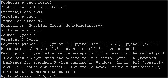
So, we assume that mouse, keyboard, monitor and Internet connection will be working. Check if your installation has already Python serial with following command on LXTerminal of Raspberry Pi desktop:
dpkg -s python-serial
If it is not installed, the response will be the following or something very similar to:
dpkg-query: package 'python-serial' is not installed and no information is available
The result you will see on Terminal screen if it is installed will be:
 Now, if it is not installed, write the following command:
sudo apt-get install python-serial
After duly installing we are ready to connect our setup of chipKIT Digilent uC32 board and Basic I/O shield with USB to mini-B cable to Raspberry Pi! But, do not connect yet!
c) Connect chipKIT Digilent uC32 with BASIC I/O shield to Raspberry Pi
On Terminal of Raspberry Pi write:
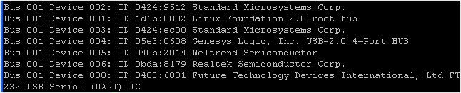
lsusb
You will get a response similar to following:
 I have an USB hub. where all my USB connections are made. I also have installed a TP-Link wireless dongle.
Now connect chipKIT Digilent uC32 board to Raspberry Pi board with USB cable.
On Terminal write again:
lsusb
And the response now will be:
 Our chipKIT Digilent uC32 is recognized as having a FTDI serial IC.
We can check a bit more with the following command:
dmesg | tail
The response will be similar to following:
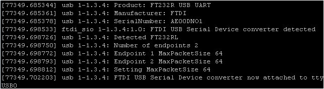 The last bit is what interests us. We have identified our recent connection as ttyUSB0 (it can be 1 or 2 or whatever is your setup). We will use this information for next part of our Procedure.
Before anything else we will install Minicom if you have not already installed. You can read in b) how to check if it is installed with following command:
dpkg -s minicom
If it is not indtalled, write the following command:
sudo apt-get install minicom
After installation run the following command:
minicom -b 9600 -o -D /dev/ttyUSB0
If all is well with your setup you will see the following on Terminal:
 Alert is shown because we have this feature enabled and our temperature is over 24ºC threshold defined in our chipKIT Digilent uC32 firmware.
We are now ready to write the Python program.
d) Write Python program for reading and displaying serial code
In /home/pi of your Raspberry Pi write the following code and name it tempmon.py. You can use the default nano editor.
#!/usr/bin/python
#tempmon.py

# Graphical User Interface for TCN75A sensor

# Imports
import time
import serial
from Tkinter import *

# Serial port parameters
serial_speed = 9600
# Your serial port instead of ttyUSB0
serial_port = '/dev/ttyUSB0'

ser = serial.Serial(serial_port, serial_speed, timeout=1)

# Main Tkinter application
class Application(Frame):

    # Measure data from the sensor
    def measure(self):

          # Request data and read the answer
          data = ser.readline() # read data from serial
          # port and strip line endings

          # If the answer is not empty, process & display data
          if (data != ""):
               processed_data = data.split(',')
               self.tempC_data.set("Temp. in " + unichr(176) + "C: " + str(processed_data[0]))
               self.temperatureC.pack()

               self.tempF_data.set("Temp. in " + unichr(176) + "F: " + str(processed_data[1]))
               self.temperatureF.pack()

               self.alertT_data.set(str(processed_data[2]))
               self.alertT.pack()

          # Wait 1 second between each measurement
          self.after(5000,self.measure)

    # Create display elements
    def createWidgets(self):

              self.temperatureC = Label(self, textvariable=self.tempC_data, font=('Verdana', 24, 'bold'))
              self.tempC_data.set("Temp in C")
              self.temperatureC.pack()

              self.temperatureF = Label(self, textvariable=self.tempF_data, font=('Verdana', 24, 'bold'))
              self.tempF_data.set("Temp in F")
              self.temperatureF.pack()

              self.alertT = Label(self, textvariable=self.alertT_data, font=('Verdana', 24, 'bold'))
              self.alertT_data.set("")
              self.alertT.pack()

     # Init the variables & start measurements
     def __init__(self, master=None):
              Frame.__init__(self, master)
              self.tempC_data = StringVar()
              self.tempF_data = StringVar()
              self.alertT_data = StringVar()
              self.createWidgets()
              self.pack()
              self.measure()

# Create and run the GUI
root = Tk()
root.title('Aliatron Office')
app = Application(master=root)
app.mainloop()
Now run this code saved as tempmon.py
python /home/pi/tempmon.py
You will see immediately the TKinter graphical interface showing the temperature as the following photo shows:
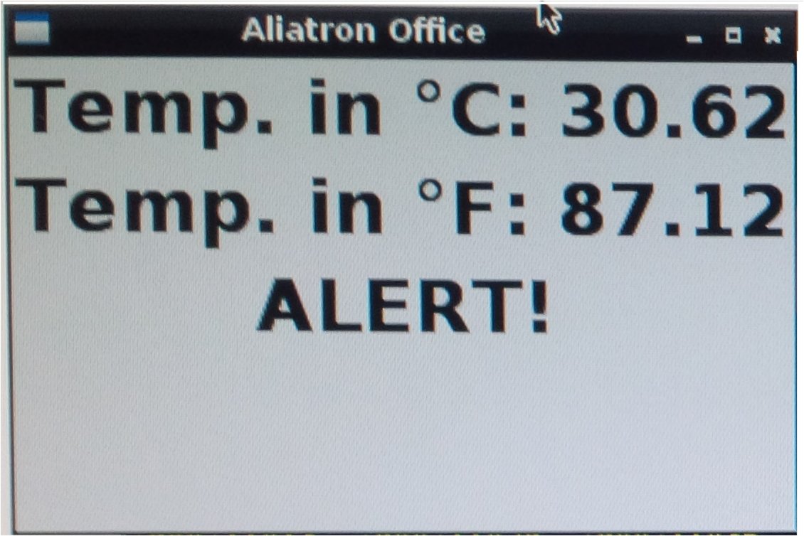 My setup is as following photo shows:
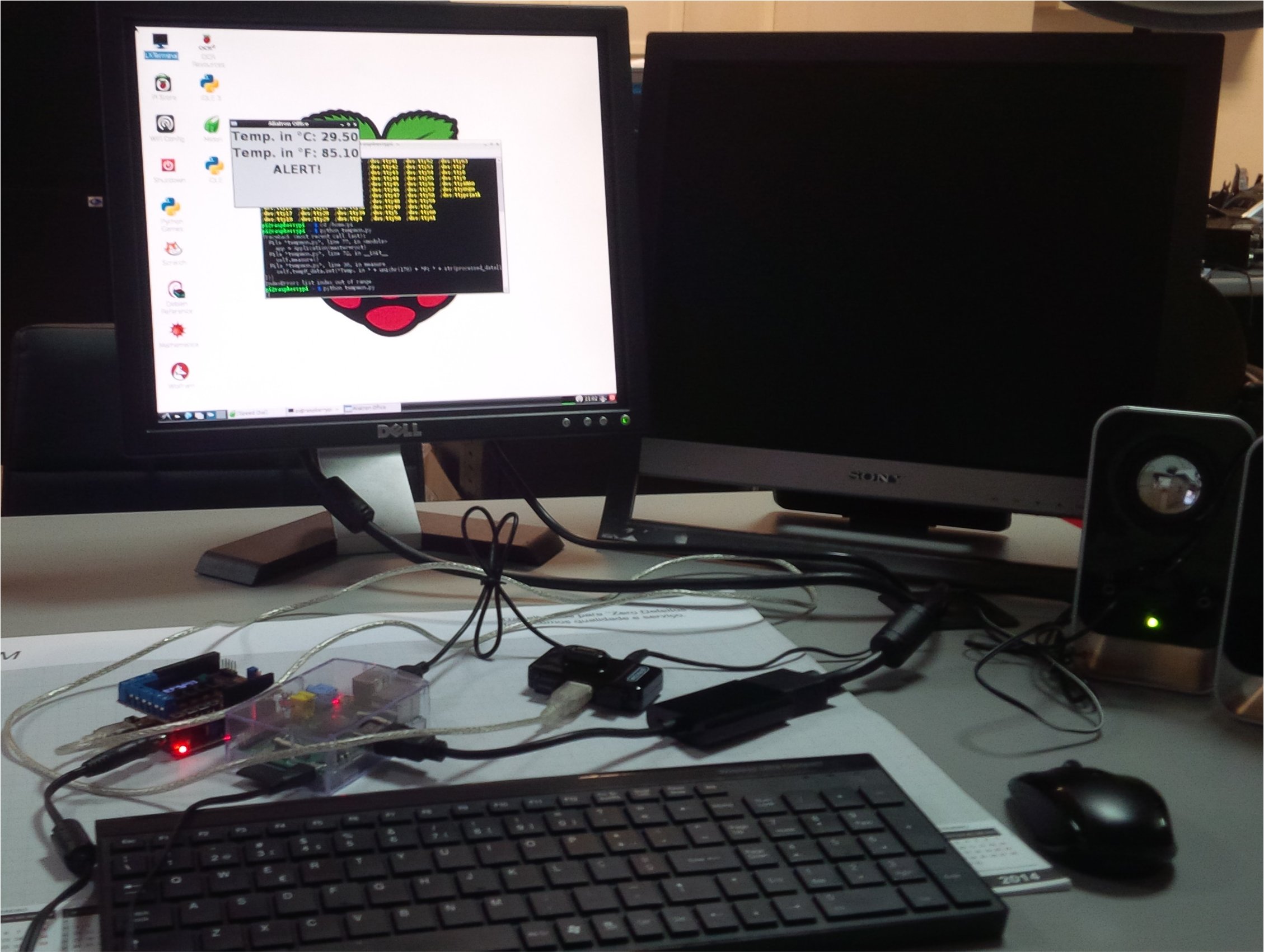
 A view of the the whole setup:
What next?
In fact imagination and resources are the limit. When threshold temperature Raspberry Pi could connect to my gmail account (or another specially opened) and send me the readings and alert information. A server can be set up and with IP forwarding one can monitor the temperature values from outside. A camera can stream images of the whole process. What else? I invite the next person to experiment with my set up and to follow my tutorial to post here his extra work.
Conclusions
Connecting up Raspberry Pi with a board such as chipKIT Digilent uC32 opens up a whole new range of interesting electronic projects. Microchip has already made it easy with chipKIT Pi, as mentioned at the beginning of this tutorial. Raspberry Pi offers lots of interesting and powerful solutions at low price, that can be combined with another low-priced board yet equally interesting and powerful chipKIT Digilent uC32. Digilent Basic I/O shield, that also offers more interesting electronic projects, with very same idea of connecting up with Raspberry Pi.

Nice one!
Pingback: Cloud-enabling with Exosite, local temperature with chipKIT Digilent uC32, Digilent Basic I/O and Raspberry Pi | RedAcacia
Pingback: Local Temp with chipKIT and Raspberry Pi » chipKIT Development Platform