
Introduction
The ProfiLab-Expert software allows you to develop your own digital or analogue measuring technology projects. It does not matter if you want to create analogue measurements or digital controls – you can realize it all. And for all this you do not have to write a single program-line. You create your projects just like drawing a wiring diagram. Simply add buttons, displays, etc. to your diagram and build your project step by step. ProfiLab-Expert is equipped with an integrated compiler that can create executable files for stand-alone applications that run on systems without ProfiLab-Expert. As an interesting act, the distribution of these compiled applications is unlimited, so ProfiLab-Expert becomes a complete and professional developers system.
The Digilent chipKIT uC32 board is based on the popular Arduino™ open-source hardware prototyping platform and adds the performance of the Microchip PIC32 microcontroller. This board is the same form factor as the Arduino™ Uno board and is compatible with many Arduino™ shields. It features a USB serial port interface for connection to the IDE and can be powered via USB or an external power supply. The uC32 board takes advantage of the powerful PIC32MX340F512 microcontroller. This microcontroller features a 32-bit MIPS processor core running at 80Mhz, 512K of Flash program memory and 32K of SRAM data memory.
Objectives
A Front Panel can be quite an interesting proposition in controlling a ChipKIT uC32 board, and that is what we will do here We will program uC32 to switch on and off LEDs on Basic I/O board, design a Front Panel in ProfiLab-Expert to control uC32 board.
Requirements
- Digilent chipKIT uC32 with Digilent Basic I/O shield on top, and power supply


Pre-Requirements
Basic knowledge of Digital Electronics.
MPIDE software for programming chipKIT Digilent Uc32 board must be installed in your PC. Also ProfiLab-Expert 4.0 valid license must have been already installed.
Procedures
A) The hardware setup
Install the Basic I/O shield on top of UNO32 as shown on the above image . Connect to the PC with USB cable. USB connection will power UNO32 and the Basic I/O shield simultaneously.
We assume that you have already installed MPIDE environment.
You will need to know the location of MPIDE sketches folder:
Run MPIDE![]()
Now do File -> New and write a new Sketch:
/*
This program switches the digital pins of the arduino Uno based on a
command sent by a connected PC via the RS-232/USB interface.
The syntax is [PinNo],[status]\n. PinNo ranges from 2 to 13 and the
status can be 1 (High) or 0 (Low). Example: 5,1\n sets the PIN 5 to
High, whereas 5,0\n sets it to Low.
Written by Benjamin Roeben; used examples: 'Blink' and
'ReadASCIIString'.

Adapted for Digilent chipKIT uC32 and Basic I/O boards by Tayeb
Habib tayeb.habib@gmail.com htt://redacacia.me

*/

void setup() {
  // initialize serial:
  Serial.begin(9600);
  // switch the pinmodes of pins 26 to 33 to OUTPUT
  for(int i=26; i<=33; i++) {
  pinMode(i, OUTPUT);
  // switch off the LEDs on Basic I/O board
  digitalWrite(i, LOW);
  }
}

void loop() {
  // if there's any serial available, read it:
  while (Serial.available() > 0) {

     // look for the next valid integer in the incoming serial
     // stream:
     int pinNo = Serial.parseInt();
     // do it again:
     int state = Serial.parseInt();
     // look for the newline. That's the end of the sentence:
       if (Serial.read() == '\n') {
         //Set the Pin states
           if (state==1)  {
           digitalWrite(pinNo, HIGH);
           }
           if (state==0)  {
           digitalWrite(pinNo, LOW);
           }
       }
     }
}
Save this sketch as ControlLEDs.pde
Make sure of serial port to which the board is connected.
Now we are ready to upload the Sketch to the uC32 board. Click the Upload button ![]() on MPIDE environment.
on MPIDE environment.
If successful you will see the following results at bottom of MPIDE environment: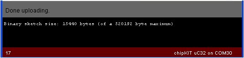 Note that for my case chipKIT uC32 is connected to COM30.
We are now ready to make our Front Panel in ProfiLab-Expert 4.0
B) ProfiLab-Expert project
Start a new project in ProfiLab-expert 4.0 File – > New.
Next in Control elements choose Digital controls
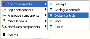 In Digital controls choose Switch
 ![]()
We can see the Switch on the Front Panel by clicking Show front panel ![]() :
:
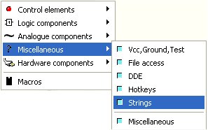
 We will leave the toggle switch for now to be changed later and proceed with the data input defining them. The switch will behave as a simple Data Selector. In Miscellaneous choose Strings:
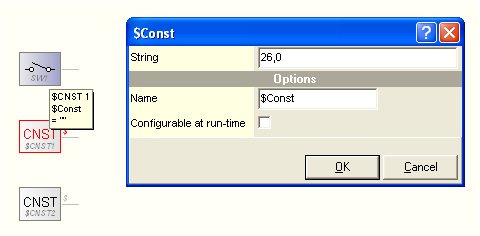
Now choose $Const ![]() as we will be dealing with string constants. It will be dropped into Workspace. Do the action a second time in order that another string constant drops into Workspace. Align them adequately to look like as follows:
as we will be dealing with string constants. It will be dropped into Workspace. Do the action a second time in order that another string constant drops into Workspace. Align them adequately to look like as follows:
 We are now ready to define these constants which will be two different data selector inputs. Click twice over first String Constant component CNST, and in pop up window, write the value of String 26,0 which means PIN26 on uC32 is OFF (check the uC32 Sketch we have just written)
 Click OK. Do the same with second Constant component CNST and write the value of String 26,1 which means PIN26 is ON, and click OK to close the pop up window.
Now we need to pass this through a Multiplexer (MUX), which in effect is a Data Selector . This is found also in Miscellaneous -> Strings, it is called $Multiplexer:
 Just click on the icon, and the component will be placed in Workspace. Right click onto it, and choose Properties:
 In pop up window, choose two channels as each switch can be either ON or OFF, i.e. these two states will be the data inputs.
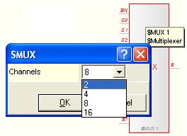 Choose 2 for number of Channels and click OK, and the pop up will close, and the result will be as shown:
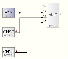
 Now connect the Switch and the two Constants, clicking the Connect button
 ![]() and connect as follows:
and connect as follows:
 Now select the whole circuit, and duplicate from menu with Edit -> Duplicate. Do this eight times until you have all of 8 circuits that are required:
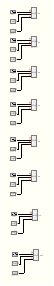 I have zoomed out the image in order to show all eight Data Selector circuits.
Now we are ready to define the constants in each Data Selector. On second Data Selector from top onwards click on CNST and change the values to 27,0 and for second CNST change to 27,1, and do so, for all Data Selectors, until the last two that will have constant values of 33,0 and 33,1.
As this juncture it is advised to save the project. Give it a name, may be profilab_uC32.prj.
We will join together all Data Selectors into a new Multiplexer (MUX) for Parallel-to-Serial Conversion. The Multiplexer is found as mentioned before in Miscellaneous -> Strings, and it is called $Multiplexer:
Just click on it, and it will be placed in Workspace. The default Properties are 8 channels as seen before, so we do not need to change the Properties.
Now connect all Data Selectors to this Multiplexer as shown below:
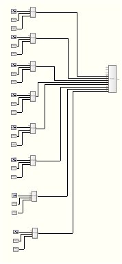 I have zoomed out the image to show all the connections.
For Parallel-to-Serial Conversion we will add now a Decade counter. This is found in Logic Components -> Counter
 Choose Decade counter (4-bit):
 Just click on it, and it will be dropped into Workspace.
We also need to add a Clock. We will add a Pulse generator 1Hz…10kHz ![]() . This is found in Logic components -> Timer
. This is found in Logic components -> Timer
 Click on Pulse generator 1Hz…10kHz. and it will also drop into Workspace. Click on Pulse generator component, and define clock as 10Hz:
 Now connect the Pulse generator to the Counter, and the Counter to Multiplexer, as shown:
 Now we are ready to add Rs232 communication. The RS232 component is named COM Send string
 ![]() and is found in Hardware components -> RS-232:
and is found in Hardware components -> RS-232:
 Choose the component by clicking on it. RS232 component will be placed in Workspace. Next connect as shown. To synchronize with the Multiplexer we will also connect the Function generator component to RS232 component:
 We are now ready to work with the Front Panel. The switches will be stacked on top of each other. Just push them sideways as shown, and rearrange them so that SW8 will be on the extreme right side, and SW1 on extreme left side:
 Toggle switches are not very convenient to indicate the status of the LED on the Basic I/O board so we will change each one to another type of switch say “Plastic lamp switch”:
 Do with every Switch, and change Hint with “LED number” on uC32. So SW1 will be “LED26”, and so on. The final result will be as shown:
 We are now ready to test and to debug our project in ProfiLab-Expert 4.0. Before you do anything else, we need to define the port and baud rate. Double click on COM component in order to configure the COM port. In my case the port is COM30, in your case t may be another that you used to program your uC32 board:
 Change the Frame value under Options clicking on
 ![]() button. In pop up window change Suffix (send after data) to 10 and the rest is as shown in image:
button. In pop up window change Suffix (send after data) to 10 and the rest is as shown in image:
 Click OK. The window will close. And now, you can you click OK the Properties pop up window, without changing any other parameters, and the window will close.
Save the ProfiLab-Expert project.
C) Testing and debugging the Project
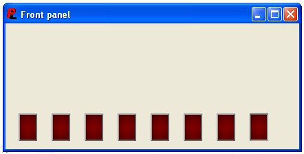
Make sure that uC32 board with Basic I/O board on top is connected to the PC. Next in Profilab-Expert 4.0 Run the project clicking on Start ![]() button or F9 key on your PC’s keyboard. The Front Panel will pop up:
button or F9 key on your PC’s keyboard. The Front Panel will pop up:
 Now we can test our Project. Just click the leftmost button, and you will see LED26 on Basic I/O light up. The button will become RED as result of our clicking. If we click again the button, it will become DARK red, and the LED26 will switch off. The following image shows the button in ON status:
 The photo below shows my actual set up with the LED26 in ON state:
 Test all other buttons on Front Panel. All of buttons should work. If not, either the circuit of the ProfiLab project has some wrong or bad connections, or parameters have not been defined correctly. You can verify pin status with Show pin status
 ![]() which will show circuit animation, and pointing a node with the mouse, you will see actual values there. The following image shows pin status $=26,1 on output pin of $MUX1:
which will show circuit animation, and pointing a node with the mouse, you will see actual values there. The following image shows pin status $=26,1 on output pin of $MUX1:
 You can label the buttons and order a bit more the buttons on the From Panel to look like the following image:
 Do a final test to make that the Front Panel displays correctly.
Demonstration of the Project
I have published a video in YouTube, that shows the simulation of the Project and the Front Panel controlling a chipKIT uC32 board with Basic I/O. You will notice that right at the beginning I have slowed down the rate of the last stage of Parallel-to-Serial conversion to 1Hz. So here is the video:
What’s Next?
1) You can add Remote Control with Bluetooth, as I have shown with previous tutorials found in this blog, so that Front Panel will control uC32 at a distance.
2) Add more features to your Front Panel, using other resources and components in ProfiLab-Expert 4.o
3) Make stand-alone application of the Project that runs on systems without ProfiLab-Expert making use of integrated compiler that can create executable files.
4) Run the Front Panel from the Web making use of PL Webserver that can be supplied together with ProfiLab-Expert 4.0. The web page can be password protected so your application will not run by unauthorized persons.
Acknowledgments
A special thank you is due to the authors of ideas porposed in Arduino – Digital Output discussion of Abacom-online forum.
Conclusions
We have shown that one can design a Front Panel with ProfiLab-Expert 4.0 without any programming as such and to control a powerful microcontroller board such as Digilent ChipKIT uC32. We have used step by step method to show all that needs to be done to launch a Front Panel. Of course a Basic Digital Electronics knowledge is required.
