
Overview
NI Multisim (formerly MultiSIM) is an electronic schematic capture and simulation program which is part of a suite of circuit design programs, along with NI Ultiboard. Multisim is one of the few circuit design programs to employ the original Berkeley SPICE based software simulation. Multisim was originally created by a company named Electronics Workbench, which is now a division of National Instruments. Multisim includes microcontroller simulation (formerly known as MultiMCU), as well as integrated import and export features to the Printed Circuit Board layout software in the suite, NI Ultiboard.
Multisim is widely used in academia and industry for circuits education, electronic schematic design and SPICE simulation. (1)
The Programmable Logic Device (PLD) Schematic in NI Multisim enables students to easily learn digital concepts by using familar digital gate logic to translate boolean logic to symbols/simulation. The PLD schematic can also export and translate digital logic into raw VHDL that can be used to program field-programmable gate array (FPGA) technology used extensively in laboratories to reinforce this theory.
Digilent Inc. is a leading electrical engineering products company serving students, universities, and OEM’s worldwide with technology-based educational design tools. Digilent offers a wide array of FPGA boards used by educational institutions to help reinforce such theory.
The combination of NI Multisim and Digilent FPGA boards offers now a new and powerful opportunity in quickly implmenting simple to medium sized logic circuits.
Objectives
Show step by step how to desing a digital logic circuit in Multisim, simulate, and for proof of concept export as raw VHDL and with specially developed configuration files that program a Digilent Basys2 Spartan-3E FGPA board.
Pre-Requisites
You must have done or at least browsed through another two tutorials published here:
Hardware Requirements
- Digilent Basys2 Spartan-3E FPGA Board (the board comes with an USB programming cable)
 Software Requirements
- NI Multisim 13.x Education Edition (to download an evaluation edition, please click here)
- ISE WebPACK Design Software (available here)
- Xilinx iMPACT 13.x or later, part of the ISE WebPack (link as shown in previous line)
Installation Instructions
- Download the attached DigilentBasys2 file.
- Unzip the file to your local disk.
Two files will unzipped: DigilentBasys2.mspc and DigilentBasys2.ucf.
- Copy and paste the two unzipped files to the pldconfig folder in the main Multisim install directory, by default, this should be:
C:\Program Files\National Instruments\Circuit Design Suite 13.0\pldconfig
In my PC it looks like as show using WinRAR (evaluation copy):

Pressing OK the files will be duly copied.
Design and Simulation
We are going to design a Car Alarm. The alarm circuit will light up a LED (Led_0) on Basys 2 board board only when the key (sw_0) is in the ignition and either the door (sw_1) is open or the seatbelt (sw_2) is not fastened. The variables are:
Hence the Truth table is:

Truth Table of Car Alarm
Where A = Door, B= Key and C = Belt
The Karnaugh map of this Truth table is:

Karnaugh Map of Car Alarm
The resulting Boolean expression is Y = A’B + BC’ which translated into logic circuit is:

We will next simulate and test the Truth table in MultiSim 13.0.
Procedure
- Run Multisim 13.0. Start a new design in menu File -> New
- Start a new PLD design, selecting File > New

Select PLD Design and click on Create
- This will start the New PLD Design Wizard. By default it will show NI Digital Electronics FPGA Board. In drop down menu we will choose Digilent Basys2.

- Click Next > button. In Step 2 we will give a name to our PLD Schematic. I have called it “myCarAlarm”

- By default Step 2 will show the PLD part number for Basys2. Click Next > button
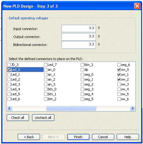
- Check Led_0, sw_0, sw_1 and sw_2. and click the Finish button. The reult will be an empty schematic with input and output

We will now use test and measurement tools in Multisim to generate the Boolean expression from Truth table, and then obtain our respective logic circuit.
- Bring into Multisim workspace Logic converter instrument by pressing onto the icon forLogic converter found at instruments’ tool bar on the right side of Multisim worksapce. The image on workspace looks like this:

- Press onto the Logic converter instrument and you will see the conversion setup.

Fill up the Truth table by pressing onto A, B, and C buttons and change the question marks of results ? into respective 0s or 1s according to the Truth table at the beginnng of this post, and as shown in the image above. Now press the button:

The result will be:

Boolean expression obtained from Truth table
This resulting Boolean expression A’B + BC’ is exactly the same as we obtained manually from Karnaugh map at the beginning of this post.
- We are now ready for the automatic logic conversion offered by Multism 12.0. Press onto the button:

It will result in the same circuit as we have obtained manually at the top of this post from Boolean expression.

- We are now ready to simulate, and test the logic circuit. Bring into Multisim workspace Word generator instrument by pressing onto the icon of Word generator found at the instruments’ tool bar on the right side of Multisim workspace. Connect up the Word generator as shown and place the Probe found at the icons bar below the menu bar at top of the workspace (note the input connectors in image have been moved to order sw_1, sw_0 and sw_2 – sw_0 is Key in our logic):

Press onto Word generator instrument. We will set the right word pattern. Press onto Set button:

Intial window. Press Set.. button to set up
The set up window will open. Change the Buffer size to 0010 and in Preset patterns chooseUp counter:

Press OK button. You will see the following window:
In Controls press Step button and in Display choose Binary. After you have done this, close the Word generator‘s window.
We are ready to simulate. Open the Word generator press onto the Step button and certify that the Truth table we have decided upon earlier is what is seen in the simulation:

As in our original Truth table, the logic circuit will behave as expected and results can be seen step by step on the Probe lighting up or switching off. We are now ready to export the Multisim circuit to VHDL.
- Connect the logic circuit as shown, and remove the Word generator instrument, the Probeas well as any other remnants of our simultaion:
Layout and connections before export to Basys 2 FPGA board

We are ready now to export and program our Basys 2 board. Save the schematic before you do anything else with File > Save
Export the PLD Logic
There are three options for exporting the digital logic from the PLD schematic:
– Programming the connected Hardware – allows students to deploy the digital logic and learn the response of using the hardware.
– Generate a PLD bit file – students can take this away and deploy when they have the hardware available.
– Generate VHDL file – allows students to explore the VHDL behind the logic.
We will focus on programming the connected hardware.
- Make sure that your Basys 2 board is connected to your PC with USB cable that comes with it.
- Select: Transfer » Export to PLD from the menu bar. Here you will see the three export options. We want to export to physical hardware so select Program the Connected PLD.
NOTE: If you are in a different language Windows OS, like I am, you will need to edit the TEMP and TMP localization in My Computer -> Properties -> Advanced -> Environment Variables, from %USERPROFILE%\Local definitions to %SYSTEMROOT% to avoid XST Synthesis failure as the command lines of compilation do not accept foreign language characters such as ç, õ and others. Of course you will need to restart your PC, after changing Windows’ Environment Variables.

We want to program the connected PLD. Click Next.

In my environment I have already installed Xilinx ISE Design Suite 14.2. Note that Device Status is not checked. Make sure first of all that Basys 2 board is connected. You may need to install Adept software and make sure that the board is recognised by your PC.
- Click on Refresh button. Multisim will try to detect the Basys 2 board. Note that Multisim 12.0 does not detect the board.

If detected you will see the following reassuring information on this step.

- Now click Next. You will see first of 11 steps that Multisim will go through

If all goes well your Basys 2 board (or any other supported Digilent boards such as Nexys – you will need to install in Multisim the adequate constraints files as you may have done with Basys 2) , you will see the following reassuring result:

- You are now able to test the logic on Basys 2 using our Truth Table:
A = sw_1, B = sw_0 and C= sw_2. So if you have the key in ignition i.e. sw_0 = 1, i.e. switch sw_0 is ON (pulled up on Basys 2 board), Alarm (Led_0) will sound (Led_0 will be ON) unless seat belt is fastned and door is closed.
We are now all done! Mission accomplished!
Conclusions
We have shown that one can easily combine Multisim’s industry-standard, best-in-class SPICE simulation environment with Digilent’s technology-based educational design tools such as entry-level Basys 2 FPGA board. Implementing on the board the logic circuit designed in Multisim is now made quite easy as we have learnt.
Resources
(1) http://en.wikipedia.org/wiki/NI_Multisim

I work for Digilent Inc and want to thank you for your work on this project. It has been featured on our social media.
Welcome to the blog. Thank you Caitilin. You have retweeted our tweet correct? Any other links of your social media posts will be appreciated.
Yes we retweeted your tweet. We also featured it on our Facebook page.
I saw your tweet and have seen latest tweets. Thank you for promoting my blog. My name is not Redacacia, it is Tayeb Habib. My blog’s name is Redacacia. If you check About you will see why I named my blog Redacacia.
hi Tayeb,
Good tutorial, specially the export to VHDL. is it possible to import vhdl design into multisim? If you know how to it would be great to see another tutorial on that.
thanks,
AEE
No it is not possible. This is because VHDL is a descriptive language. May be one day!
Thank you for your kind words. Will try my best to write another tutorial.