Designing, Simulating and Implementing a Simple Car Alarm on a Xilinx FPGA – Part I

Objectives

Design and simulate a simple car alarm on NI Multism 12.0 and implement on a Xilinx FPGA Spartan 3 Starter kit board from Digilent.

This is a two parts post. In this part we will design a logic circuit and simulate. In part II we will implement in an actual Xilinx FPGA.

Introduction

FPGA (Field Programmable Gate Array) is a chip containing a matrix of logic cells with programmable interconnects, which can be configured by a user. By configuring the function of each logic cell and the way they are connected between each other, one can make FPGA implement any digital circuit (limited only by the capacity of the device).

Xilinx offers the broadest portfolio of FPGAs providing advanced features, lowest power, highest performance, and highest value for any FPGA-based design. Xilinx is the world’s leading provider of All Programmable FPGA’s, SoC’s and 3D ICs. These industry leading devices are coupled with a next-generation design environment and IP to serve a broad range of customer needs, from programmable logic to programmable systems integration.

Design and simulation is facilitated by easy-to-use and intuitive Electronic Design Automation (EDA)  tool Multisim 12.0 from National Instruments. NI Multisim (formerly known as Electronics Workbench) is an electronic schematic capture and simulation program which is part of a suite of circuit design programs, along with NI Ultiboard. Multisim is one of the few circuit design programs to employ the original Berkeley SPICE based software simulation. Multisim was originally created by a company named Electronics Workbench, which is now a division  of National Instruments. Multisim includes microcontroller simulation (formerly known as MultiMCU), PLD design (exporting VHDL code) as well as integrated import and export features to the Printed Circuit Board layout software in the suite, NI Ultiboard. Multisim is widely used in academia and industry for circuits education, electronic schematic design and SPICE simulation.

Implentation is made easy in FPGA boards from Digilent. Digilent’s Xilinx-based programmable logic boards are built around the latest FPGA technologies and time-tested solutions that offer robust performance at a very low price. Most boards feature on-board USB power & programming, and cost less than the price of a textbook.

Requirements

NI Multisim 12.0
– Digilent Spartan 3 Starter Kit board
Xilinx ISE Design Suite 13.4 or superior

Design and Simulation

The alarm circuit will light up a LED (LD0) on Spartan 3 Starter kit board only when the key (SW1) is in the ignition and either the door (SW2) is open or the seatbelt (SW0) is not fastened. The variables are:

                                    Key = 0      key is not in the ignition
                                    Key = 1      key is in the ignition
                                    Door = 0    door is open
                                    Door = 1    door is closed
                                    Seat = 0     seat belt is not fastened
                                    Seat = 1     seat belt is fastened
                                    Alarm = 0   alarm is not ON
                                    Alarm = 1   alarm is ON

Hence the Truth table is:

Truth Table of Car Alarm

Where A = Door, B= Key and C = Belt

The Karnaugh map of this Truth table is:

Karnaugh Map of Car Alarm

The resulting Boolean expression is Y = A’B + BC’ which translated into logic circuit is:

Logic Circuit

We will next simulate and test the Truth table in MultiSim 12.0.

Run Multisim 12.0. Start a new design in menu File ->  New -> PLD Design…

In Step 1 choose

Create empty PLD window

Press Next > and then in Step 2 window in PLD Design name field write Car_Alarm. In PLD part number (optional) field write XC3S200 which is the FPGA on Spartan 3 Starter Kit.

Note: The option of Create empty PLD is a recent one in Multisim – it may not be available in earlier versions.

Step 2 of PLD design

Press Next > and the final step window will open

Step 3 of PLD design

Final Step of PLD Design windows

Do not change anything here. Just press the Finish button.

You will now see the Multisim workspace for PLD design. Add input and output connectors. The respective buttons are on the top left corner just below Multisim workspace’s menu bar:

Input output connectorsThe PLD design workspace should look like as follows:

Input output connector on Car_Alarm design

Change the names of these connectors to DOOR, KEY, SEAT and ALARM and rearrange the layout of the connectors in a way to have ample space between input and output connectors.

Input output connectors renamed and rearranged in workspace

We will now use test and measurement tools in Multisim to generate the Boolean expression from Truth table, and then obtain our respective logic circuit.

Bring into Multisim workspace Logic converter instrument by pressing onto the icon for Logic converter found at instruments’ tool bar on the right side of Multisim worksapce. The image on workspace looks like this:

Multisim’s Logic converter instrument

Press onto the Logic converter instrument  and you will see the conversion setup.

Truth table in Logic converter

Fill up the Truth table by pressing onto A, B, and C buttons and change the question marks of results ? into respective 0s or 1s according to the Truth table at the beginnng of this post, and as shown in the image above. Now press the button:

Button to obtain Boolean expression

The result will be:

Boolean expression obtained from Truth table

This resulting Boolean expression A’B + BC’ is exactly the same as we obtained manually from Karnaugh map at the beginning of this post.

We are now ready for the automatic logic conversion offered by Multism 12.0. Press onto the button:

It will result in the same circuit as we have obtained manually at the top of this post from Boolean expression. 

We are now ready to simulate, and test the logic circuit. Bring into Multisim workspace Word generator instrument by pressing onto the icon of Word generator found at the instruments’ tool bar on the right side of Multisim workspace. Connect up the Word generator as shown and place the Probe found at the icons bar below the menu bar at top of the workspace:

Set up for simulation of the logic circuit

Press onto Word generator instrument. We will set the right word pattern. Press onto Set button:

Intial window. Press Set.. button to set up

The set up window will open. Change the Buffer size to 0010 and in Preset patterns choose Up counter:

Set up window of Word generator instrument

Press OK button. You will see the following window:Almost there  to simulate....

In Controls press Step button and in Display choose Binary. After you have done this, close the Word generator‘s window. And now place Probe – icon found at the top menu bar – into the PLD workspace and connect the circuit for simulation as shown:

Simulation circuit with Word generator and Probe

We are ready to simulate. Open the Word generator press onto the Step button and certify that the Truth table we have decided upon earlier is what is seen in the simulation:

Simulation to proof out the Truth table

As in our original Truth table, the logic circuit will behave as expected and results can be seen step by step on the Probe lighting up or switching off. We are now ready to export the Multisim circuit to VHDL.

Connect the logic circuit as shown, and remove the Word generator instrument, the Probe as well as any other remnants of our simultaion:

Layout and connections before export to VHDL

Now on the top of workspace’s menu choose Tools -> Export to PLD…

Export to PLD window will open:

Export to PLD window

Press the button Ok and the results will be shown, hopefully without any errors or warnings:

Export results and warnings

A Car_alarm.vhd file has been exported.

Download

The Multisim simulation files and exported VHDL file can downloaded from here.

Acknowledgements

A special credit is due to Project Navigator Tutorial at Brigham Young University site, for the truth table that serves as the basis for tutorial. Our appraoch is completely different.

Conclusions

We have designed and simulated a logic circuit in Multisim 12.0 and exported the circuit as VHDL. In part II we will program and test the logic circuit in a Digilent Spartan 3 FPGA Starter kit board.

Posted in Electronic Projects, Electronic Simulation, Programming | Tagged , , , , , , | 2 Comments

Temperature Measurement with PSoC CY8C27643 and DS18B20 sensor

Objectives:

To build a thermometer, with a Cypress PSoC chip CY8C27643 and 1-wire DS18B20 temperature sensor.

Introduction

PSoC (Programmable System-on-Chip) is a family of integrated circuits made by Cypress Semiconductor. These chips include a CPU and mixed-signal arrays of configurable integrated analog and digital peripherals.

PSoC is used in devices as simple as Sonicare toothbrushes and Adidas sneakers, and as complex as the TiVo set-top box. One PSoC, using CapSense, controls the touch-sensitive scroll wheel on the Apple iPod click wheel.

PSoC is a software configured, mixed-signal array with a built-in MCU core. There are three different family of devices (2009):

  • CY8C2xxxx Named PSoC1 with CPU M8C
  • CY8C3xxxx Named PSoC3 with CPU 8051
  • CY8C5xxxx Named PSoC5 with CPU ARM Cortex M3

PSoC has three separate memory spaces: paged SRAM for data, Flash memory for instructions and fixed data, and I/O Registers for controlling and accessing the configurable logic blocks and functions. The device is created using SONOS technology.

PSoC resembles an ASIC: blocks can be assigned a wide range of functions and interconnected on-chip. Unlike an ASIC, there is no special manufacturing process required to create the custom configuration – only startup code that is created by Cypress’ PSoC Designer IDE.

PSoC resembles an FPGA in that at power up it must be configured, but this configuration occurs by loading instructions from the built-in Flash memory. Unlike an FPGA, the current generation of PSoC cannot have its digital functions reprogrammed by VHDL or Verilog, it can only be configured with register settings.

PSoC most closely resembles a microcontroller in usage, where code is run to interact with the user-specified peripheral functions (called “User Modules”), using automatically generated APIs and interrupt routines. The PSoC Designer IDE generates the startup configuration code and peripheral APIs automatically based upon the users selections in a Visual-Studio-like GUI.

Cypress offers a visual, code-free embedded design tool for PSoC called PSoC Express. Using PSoC Express, most features of the PSoC can be accessed with drag and drop icons and logical expressions. The visual design is compiled to executable code without exposing the user to the underlying converted code, though a visual design can be converted and used as a basis of a traditional code-based design in PSoC Designer. Visual design elements cover features such as temperature sensors, fan control, accelerometers, I2C master and slave protocols, USB virtual serial ports, capacitive sensors, and wireless 2.4 GHz radio communications.Cypress Semiconductor introduced a new family in it’s PSoC 3 architecture. Programmable Digital PSoC 3 Family allows the integration of digital peripherals along with PWMs, Timers, Counters, UARTs, glue logic and state machines.It also offers customizable digital functions and interfaces, which lowers overall system power by migrating traditional CPU functions to programmable digital logic.

Required Equipment:

Mikroelektronica’s EasyPSoC4 Development Board, Dallas 1-wire sensor DS18B20 and LCD 2×16 (these last two devices are supplied with EasyPSoC4).

Pre-Requirements:

Needless to say one must have some C-language programming knowledge, and basic notions of  PSoCs, namely about the Cypress chip CY8C27643. PSoC Designer must be already installed in one’s PC, with C-language programming from Imagecraft default option (Imagecraft allows free usage for 45 days).

Building the Circuit:

On EasyPSoC4 board (which includes as standard the Cypress CY8C27643 PSoC DIL), install the 2×16 LCD and DS1820 temperature sensor (both included with the kit). Ensure that the display GLCD is not mounted on EasyPSoC4.

DS1820 mounted on EasyPSoC4

Fig. 1 circuit diagram of DS18B20 mounted on EasyPSoC4 board

NOTE: Switch 1 of SW3 should be placed in the ON position (and switch 2 OFF), as in this application we will be using port P0-2 of the PSoC to connect the DS1820 sensor) .

Fig 2: Circuit diagram showing connections between the temperature sensor and LCD 2×16

Experiment:

1 – Installation of  1-wire module 

If 1-wire module is not already installed in PSoC Express software, it is available on Cypress site at:

http://www.psocdeveloper.com/uploads/media/OneWire_v1.3.3.zip

Place OneWireSW  zip in C:\Program Files\Cypress MicroSystems\PSoC Designer\Data\Stdum, and afterwards run Cypress Expresssoftware . Close any open project. Run Refresh Manifest which is found in menu Tools, so that the module becomes available.

2 – Project

a) Start a new project in PSoC Designer, giving it a name, say for example DS1820. The software will ask you if you want create a new directory, to which you will respond pressing on Yes button. In the following screen we choose C, pressing the button to  conclude.

In PSoC Designer choose LCD, which is found inside Misc

Digital of the module User Module Selection, pressing twice over the LCD icon. Next choose OneWireSW which is found within Digital Misc of the User Module Selection, pressing twice over the OneWireSW icon.

Selected User Modules will contain both icons, as can be seen:

Press the button (Interconnect View)

so that you can setup the connections within PSoC.

For on OneWireSW the following selections are made:

For LCD the following selections are made:

In Gobal Resources change the clock to 12_MHz (Sys_Clk/2), leaving out the rest of parameters as they appear:


e) Next, press the button (Generate Application)

The PSoC Designer will generate the applications.

f)  Now, press the button (Application Editor)

Within the folder1820 files and sub-folder Source files, open the file main.c. It will contain a default code generated automatically. Substitute the code with  following code:

//----------------------------------------------------------
// C main line
// Themperature Measurement with DS18B20
// Author: Tayeb Habib – https://redacacia.wordpress.com
// Adaptation from http://narong.engr.tu.ac.th/microlab/doc 
//---------------------------------------------------------------- 
#include         // specification of constants and macros
#include "PSoCAPI.h"    // Definitions of PSoC API for all modules
#include 

char TextBuff[5];
unsigned char TLSB, TMSB, TempI;
int TempP;

void main()
{
    LCD_1_Start();
    LCD_1_Position(0,0);
    LCD_1_PrCString("1-Wire & DS18B20");
    OneWireSW_1_Start();	            //initiates 1-Wire 

    while(1)
    {
        OneWireSW_1_Reset();	            //reset of 1-Wire
        OneWireSW_1_WriteByte(0xCC);        //skip ROM 
        OneWireSW_1_WriteByte(0x44);        //temperature conversion 

        OneWireSW_1_Delay10mTimes(90);      //waits 900ms for
                                            //conversion

        OneWireSW_1_Reset();	            //reset of 1-Wire
        OneWireSW_1_WriteByte(0xCC);        //skip ROM  
        OneWireSW_1_WriteByte(0xBE);        //Scratch Pad reading 
                                            //instruction 
        TLSB = OneWireSW_1_ReadByte();      //read LSB data
        TMSB = OneWireSW_1_ReadByte();      //read MSB data
        TempI = (TLSB >> 1) & 0x7F;
        TempI = TempI | (TMSB & 0x80);      //temperature whole
                                            //numbers format
        TempP = TLSB & 0x01;	            //binary point 
                                            //of temperature
        itoa(TextBuff,TempI,10);	    //data conversion to 
                                            //ASCII 
        LCD_1_Position(1,0);	            //position on LCD 
        LCD_1_PrCString("Temp =  ");        //write data on LCD 
        LCD_1_PrString(TextBuff);

        TempP = TempP * 5;	            //convert to decimal 
                                            //point
        itoa(TextBuff,TempP,10);           //show decimal point
        LCD_1_PrCString("."); 
        LCD_1_PrString(TextBuff); 
        LCD_1_PrCString(" C ");
    }

And finally press the e button (Build)

The resultcan be on the window Build in the lower part of PSoC Designer workspace,

Starting MAKE...
creating project.mk lib/lcd_1.asm lib/onewiresw_1.asm lib/psocconfig.asm lib/psocconfigtbl.asm
./boot.asm
./main.c
Linking..
ROM 13% full. 2088 bytes used (does not include absolute areas).
RAM 8% full. 23 bytes used (does not include stack usage).
ds1820 - 0 error(s) 0 warning(s) 15:37:06

ds1820.hex is generated, which will be now used n programming he PSoC on the EasyPSoC4 board. After the hex is uploaded, the LCD 2×16 will show room temperature, which you can change by touching  DS18B20 with a finger.

Final considerations

Add a buzzer to the ircuit so  that PSoC will play a tone, everytime the DS18B0 reads a certain temperature that has been predefined by you.

References

PsOC Products

CY8C27643 chip

OneWire v1.3.3..zip


Posted in Electronic Projects, Electronic Simulation | Tagged , , , , , , , , | 6 Comments

BlueTerm app for most Android devices

Introduction

Having “hacked” into BlueTerm source code to make it work with my HTC clone,  known as A3 Star (HD2 T8585 clone), I thought why not make the mod in order that BlueTerm will function in most Android devices with bluetooth, if not all, and permit download of modified app to those web surfers and regular visitors to my blog that are not knowledgeable enough about programming, and specially in working with the Eclipse environment. The “hack” and how it is done is explained in my previous post.

The modded BueTerm app

I have followed the approach  of Bluescripts. The author of Bluescripts app has used BlueTerm as source code and modified for his app that uses a XML file that is displayed on the Android device’s screen with buttons to control external bluetooth modules via bluetooth.

The modded app, renamed just for installation to Blueterm_RM.apk, (RM stands for Reflection Method, the method I used to make bluetooth connection with my HTC clone)  is avaliable for download  at the end of this post, with my respective disclaimer. Please read the disclaimer, as by downloading the software (i.e. the app) you are accepting the terms and conditions of my disclaimer.

When the app is run, and after due pairing, it effectively tries to connect in conventional default manner to the external device (in my case I tested my app with  my Bluetooth module). If connection fails, it uses a fallback method (Reflection method as shown here in this blog).

The rest of the app, functions as BlueTerm does. My tests make me confident enough to make it available for download. In order to install my unsigned app, you will need to allow for unknow sources installations in your Android phone in :

All Apps -> Settings -> Application -> Unkonwn sources     and tick the square box.

The downloadable modded BlueTerm app

Here is the the download link Blueterm_RM.apk. This file is hosted at Bitbucket a site that offers unlimited public and private repositories and it is free for small teams.

Please read the disclaimer at the end of this post. By downloading this app you have accepted the terms and conditions of the disclaimer.

Download the app to your desktop, and then copy to your Android phone’s SD card, or download directly to your Android phone. Install it by conventional method, running it with say free explorer apps available on Android App market, and hopefully you will have a modified version of BlueTerm that will work with any Android device with bluetooth.

Disclaimer

THE SOFTWARE (“APP” OR “THE AP”P AS IT IS REFERED TO IN THIS POST) IS PROVIDED “AS IS”, WITHOUT WARRANTY OF ANY KIND, EXPRESS OR IMPLIED, INCLUDING BUT NOT LIMITED TO THE WARRANTIES OF MERCHANTABILITY, FITNESS FOR A PARTICULAR PURPOSE AND NONINFRINGEMENT. IN NO EVENT SHALL THE AUTHORS OR COPYRIGHT HOLDERS BE LIABLE FOR ANY CLAIM, DAMAGES OR OTHER LIABILITY, WHETHER IN AN ACTION OF CONTRACT, TORT OR OTHERWISE, ARISING FROM, OUT OF OR IN CONNECTION WITH THE SOFTWARE OR THE USE OR OTHER DEALINGS IN THE SOFTWARE

Posted in Mobile Apps, Programming | Tagged , , , , | 41 Comments

Overcoming Android bluetooth “blues” with Reflection method

Introduction

It is an Android problem: bluetooth does not function in a satisfactory manner. Having recently  started to “hack” into Android devices, and learning while doing, I was immediately confronted with the real world of something that does not fully work (bluetooth in Android devices) at least not satisfactorily as with J2ME devices I worked with before (Nokia and Blackberry).  It is worse if you do, as I did, in buying an Android smartphone in China (A3 Star, HTC T8585 clone) . You will be immediately confronted with the merchants that are insensitive to your requests for technical support. Effectively you learn immediately that there is nobody out there to talk to.

Android bluetoooth “blues”

When I connected my Android phone to external devices, in my case a bluetooth module, the immediate response was an “unable to connect” toast. “Googling“ made me desperate when the enormity of information confused me even more. How to approach the problem, what is wrong with my cheap chinese Android phone? MediaTek the chipset manufacturer of the device’s processor does not “leak” out any source codes to be able to hack bluetooth libraries for example.

Reflection method – solution to connection problem

If you seek quality technical responses I advise you Stack Overflow. That is where I finally learnt a few things such as the problem of connection is overcome with Reflection method.

Technically-speaking the reason is that the widely used connection method CreateInsecureRfcommSocketToServiceRecord() was only included starting with Android API Level 10. When targeting an API lower than 10 (ex 2.3.3 or Gingerbread), the method is not publicly accessible. The Reflection method overcomes that.

So in my chinese HTC clone “A3 Star” I have now a fully working Android market’s BlueTerm, a free app that I use for my engineering tests with external devices. I had to hack into BlueTerm´s source code (it is publicly available at http://pymasde.es/blueterm/) in order to change the method of connection to the Reflection one.

Looking into libraries of my phone’s processor MTK6573, I noted that they were made in 2008, and were never updated. Perhaps in China (the primary target of MTK processors) they do not use SPP at all, and are insensible to “techie“ learners like me wanting to use SPP connection in bluetooth.

On Reflection method among others, you can read more at Stock Overflow site

The code mod made to BlueTerm app

Additionally a special credit is due to Teholabs and their source code for BlueScripts app and the connection method of Reflection. You need to open in your adequate Eclipse environment BluetoothSerialService.java and add at the begining of the file:

Just before:

import java.util.UUID;

Add:

import java.lang.reflect.InvocationTargetException;
import java.lang.reflect.Method;

And down in the file find:

 try {
    tmp = device.createRfcommSocketToServiceRecord(SerialPortServiceClass_UUID);
    } catch (IOException e) {
    Log.e(TAG, "create() failed", e);
    }
    mmSocket = tmp;
    }

And substitute with

  Method m;
   try {
    	m = device.getClass().getMethod("createRfcommSocket", new Class[] {int.class         });
        tmp = (BluetoothSocket) m.invoke(device, 1);  
        } catch (SecurityException e) {
    	Log.e(TAG, "create() failed", e);
    	} catch (NoSuchMethodException e) {
    	Log.e(TAG, "create() failed", e);
    	} catch (IllegalArgumentException e) {
    	Log.e(TAG, "create() failed", e);
    	} catch (IllegalAccessException e) {
    	Log.e(TAG, "create() failed", e);
    	} catch (InvocationTargetException e) {
    	Log.e(TAG, "create() failed", e);
    	}         

   mmSocket = tmp;
    }

You are now ready to compile and download the BlueTerm app into your Andorid device, hopefully without any errors.

The Results

You need to first of all to pair your Android phone to the external module. So I assume you have paired your phone to external bluetooth module. Now we are ready to start the BlueTerm app. This is the first screen you see when you start BlueTerm app:

Opening screen of BlueTerm App

First screen of BlueTerm App
showing “not connected”

We next find the paired device pressing the menu button of your Android phone and choose “Connect Device“. You will see the paired devices including the module you have just paired:

Screen showing paired device

Screen showing paired device

Choose the device and immediately BlueTerm will show the message at the top right of the screen “connecting…”.

If connection is successful the folowing screen will show with virtual keyboard to send commands:

Screen showing connected SPP

Screen showing connected SPP

To leave the application you have to press the menu button on your device and you will now have to disconnect. It is advisable to disconnect:

Screen showing disconnect device

Screen showing disconnect device

UPDATE: For non-techincal users of Android devices I have made available a ready to install BlueTerm app at my most recent post. Before downloading the apk, please read my disclaimer on the same page.

Bugs and Improvements

This mod  is quite fresh and needs to be tested further. I have had to reboot once my HTC clone as the app froze when I tried to disconnect. Any improvements and code sharing from visitors to this blog will be appreciated.

Moral of history

If you want a fully working smartphone do not buy in China, and if you really want to take the risk, check beforehand on the reliability of your supplier.

However I confess, I have an inside feeling of gratitude to the chinese, because if everything was working fine, I would have had no challenges to overcome, and would have not learnt much about Android bluetooth.  The chinese manufacturers do not make available source codes, while non-chinese manufacturers do, or have “leaked” source codes.

Source codes mean opportunities to mod and to improve and a chinese manufacturers do not seem to “leak” these codes.

Conclusions

Just as Bluescripts does the next step for me will be to connect in default way, and then in alternate way (update: I have already made a ready to install modded app of Blueterm – check above).

From now on, I will be able to write new apps for my chinese HTC clone, using Reflection method. The Reflection method is only valid for situations similar to mine.  I hope that sharing this work of mine will help others with similar error messages “unable to connect” in their Android devices.

Posted in Mobile Apps, Programming | Tagged , , , , , | 19 Comments

Android controlled robot via bluetooth

Introduction

Having recently bought an Android phone, I thought it would be a nice endeavour to control a robot with such a device.

Android being open-source, attracts a large following, and hence there are many different ready-made solutions that can be hacked into.

Required equipment

A 8051 robot “Robo-51” (could be a robot with any other micrcontroller) with ZX-Bluetooth module, running a firmware for bluetooth control, and an account with App Inventor.

Robo-51
8051-based robot “Robo-51″
Serial bluetooth module “ZX-Bluetooth”

App Inventor Code

The code is based on BennyBlue made with App Inventor. After being able to control the robot you will need to download the file Bluemote_1_0_a.zip (check the end of the article under the heading Update) that you need to upload in App Inventor’s Invent to see the full code and to compile the apk application for your Android device.  For absolute beginners the excellent resources and tutorials found in App Inventor Explore, are very good and easy to follow.

The control program

The Android application controls Robo-51 from Inex, with the commands:

Key letter “d” foward, “a” backwards, “c” turn leftwards, “b” turn rightwards and “s” stop.  The following image shows how the application looks like in my Android device(with new update – check at the end of the post under Update):

New screenAndroid Screen of Bluemote Application

Before running the application you will need to pair the serial device on Robo-51 with your Android’s bluetooth. On connecting with the robot, you will hear “I’m robo-51… I’m at your command!”. On controlling the robot, you will hear in your Android device “forward”, “backward”, “turning left” etc.

Conclusion

This project adds into existing projects in this blog, with Robo-51 and bluetooth serial control. The main aim of this project was to achieve, with little work, similar results to those obtained with Java-based Nokia N97 and Blackberry Bold 9700.  Effectively I can tick this project as successful.

——————————————

Update

The layout has been improved as can be screen on the image above . The new source file is Bluemote_1_0_a.zip, kept at Bitbucket, an unlimited free private repositories’ site.

Posted in Mobile Apps, Programming, Robotic Projects | Tagged , , , , , , , | 2 Comments

Voice Operated Internet Control of a PICAXE (Part II)

Objectives

Experiment with more advanced features offered by Picaxe microcontroller. Measure temperature through a Maxim  DS18B20   sensor and obtain interactivity with recourse to audio response using text to voice offered by Google translate.

The electronic setup

AXE050 board with Picaxe18M microcontroller is used just as in Part I. Here is a picture of AXE050:

AXE050 Board

Temperature sensor Maxim  DS18B20  is added to the AXE050 board reads temperatures. The advantage of using Picaxe18M is that the same ports are used for control and programming.

DS18B20 Pinout

PICAXE-18M and DS18B20 connections

Reading and control of AXE050 board is done using RS232 protocol. The onboard connections are used for RS232 control.

Pre-Requirements

Before carrying out this part of project, Voice Operated Internet Control of a PICAXE (Part I) must have been implemented, i.e. experimented already with simple switching of a LED on the AXE050 board. The firmware on the chip will be the same as in Part I, and the same as in Internet Control of a Picaxe published here long time ago.

RS232 control is done again in DOS environment, using Kermit for DOS. Kermit scripts are run by PHP, to control AXE050. Kermit’s executable MSK316.exe is installed in same directory as all files. As mentioned in part I, all files will be in c:\xampp\htdocs.

Note: COM2 is used  at baudrate of 4800 setup in Control Pannel of Windows XP.

Now the scripts…

STATUS Kermit script (name it status.ksc):

set port 2
set baud 4800
clear
output c=s
input /nowrap

The new command is input /nowrap, being used to obtain output from Kermit and pipe it into the server.

This script is called in a BATCH file (name it sta.bat):

@echo off
c:\wamp\www\msk316 take status.ksc
exit

TEMPERATURE Kermit script (name it gettemp.ksc):

set port 2
set baud 4800
clear
output c=t
input /nowrap

Again we use new command input /nowrap.

This script is called in a BATCH file (name it temp.bat):

@echo off
c:\wamp\www\msk316 take gettemp.ksc
exit

All batch files are then converted into .exe using Bat_to_Exe_Converter. As result, will have two new executables sta.exe and temp.exe in the folder htdocs, besides the previous part I executables ledon.exe and ledoff.exe.

Finally again the html and php codes…

Substitute index.html of Part I with new one as shown below, again within htdocs folder of Windows-based XAMPP server.

index.html

<!DOCTYPE html>
<html>
<head>
<meta http-equiv="content-language" content="en-US">
<meta charset="utf-8">

<title>Voice Operated Control </title>
<script type="text/javascript">
function checkSpeechSupport(){
var element=document.createElement("input");
if (!('webkitSpeech' in element)) {
alert("Sorry! Your browser does not support the Speech Input");
}
}
function checkanswer() {
var answer = document.getElementById('q2answer').value;

if (answer == 'light on') {

window.location.href = "http://localhost/processing.php?action=on";
}

else if (answer == 'lights on') {

window.location.href = "http://localhost/processing.php?action=on";
}

else if (answer == 'light off') {

window.location.href = "http://localhost/processing.php?action=off";
}

else if (answer == 'lights off') {

window.location.href = "http://localhost/processing.php?action=off";
}

else if (answer == 'temperature') {

window.location.href = "http://localhost/processing.php?action=tem";
}

else if (answer == 'temperatures') {

window.location.href = "http://localhost/processing.php?action=tem";
}

else if (answer == 'status') {

window.location.href = "http://localhost/processing.php?action=sta";
}

else {
window.location.href = "alert.php";
}
}
</script>
</head>
<body onLoad="checkSpeechSupport()">
<form id="speechform">
<fieldset id="inputs">
<font face="arial, verdana"><legend><h2>Voice Control of Picaxe AXE-050U:</h2></legend>
<label for="q2answer">Say commands: "light on", "light off"<br>"temperature" and "status":</label></font>
<input id="q2answer" name="q2answer" type="text" x-webkit-speech onwebkitspeechchange="checkanswer()"/><br/>
<img src="http://localhost:8888/out.jpg">
</fieldset>
</form>
</body>
</html>

Substitute processing.php of Part I with new one as shown below, again within htdocs folder

processing php

&lt;?php
// numerical to text class included
include 'num2text.class.php';
//check the GET actions variable to see if something needs to be done
    if (isset($_GET['action'])) {
    //Action has been requested
    //Issue the command we wish to send to the Picaxe

    if ($_GET['action'] == &quot;on&quot;) {
        //Turn LED on - for this simple script we are just looking for either a 1 or 0
    $page = &quot;index.html&quot;;
    header(&quot;Refresh: 4; URL=\&quot;&quot; . $page . &quot;\&quot;&quot;);
          exec ('sta.exe',$report);
           // check waht is in array $report
           // print_r($report);
          $pieces = explode(' ',$report[0]);
          if ($pieces[1] == 1) {
                echo &quot;&lt;font face=\&quot;arial, sans-serif\&quot;&gt;&lt;b&gt;LIGHT IS ALREADY ON&lt;/b&gt;&lt;/font&gt;&lt;br&gt;&quot;;
                echo &quot;<a href="http://translate.google.com/translate_tts?tl=en&#038;q=light+is+already+on!">http://translate.google.com/translate_tts?tl=en&#038;q=light+is+already+on!</a>&quot;;
          }
          else {
          exec('ledon.exe');
          echo &quot;&lt;hr align='center' size=\&quot;4\&quot; color=\&quot;orange\&quot;&gt;&lt;br&gt;&quot;;
          echo &quot;&lt;font face=\&quot;arial, sans-serif\&quot;&gt;&lt;b&gt;LIGHT IS NOW ON&lt;/b&gt;&lt;/font&gt;&lt;p&gt;&quot;;
          echo &quot;<a href="http://translate.google.com/translate_tts?tl=en&#038;q=light+is+now+on!">http://translate.google.com/translate_tts?tl=en&#038;q=light+is+now+on!</a>&quot;;
      }

      }

     else if ($_GET['action'] == &quot;off&quot;) {
     //Turn LED off
     //Now we &quot;open&quot; the serial port so we can write to it
     $page = &quot;index.html&quot;;
     header(&quot;Refresh: 4; URL=\&quot;&quot; . $page . &quot;\&quot;&quot;);
           exec ('sta.exe',$report);
           // check waht is in array $report
           // print_r($report);
           $pieces = explode(' ',$report[0]);
           if ($pieces[1] == 0) {
                echo &quot;&lt;font face=\&quot;arial, sans-serif\&quot;&gt;&lt;b&gt;LIGHT IS ALREADY OFF&lt;/b&gt;&lt;/font&gt;&lt;br&gt;&quot;;
                echo &quot;<a href="http://translate.google.com/translate_tts?tl=en&#038;q=light+is+already+off!">http://translate.google.com/translate_tts?tl=en&#038;q=light+is+already+off!</a>&quot;;
           }
           else {
           exec('ledoff.exe');
           echo &quot;&lt;hr align='center' size=\&quot;4\&quot; color=\&quot;orange\&quot;&gt;&lt;br&gt;&quot;;
           echo &quot;&lt;font face=\&quot;arial, sans-serif\&quot;&gt;&lt;b&gt;LIGHT IS NOW OFF&lt;/b&gt;&lt;/font&gt;&lt;p&gt;&quot;;
           echo &quot;<a href="http://translate.google.com/translate_tts?tl=en&#038;q=light+is+now+off!">http://translate.google.com/translate_tts?tl=en&#038;q=light+is+now+off!</a>&quot;;
           }
      }

      else if ($_GET['action'] == &quot;tem&quot;) {
           exec ('temp.exe',$report);
           $pieces = explode(' ', $report[0]);
           $n2s = new num2text($pieces[1]);
           $page = &quot;index.html&quot;;
           header(&quot;Refresh: 4; URL=\&quot;&quot; . $page . &quot;\&quot;&quot;);
           echo &quot;&lt;hr align='center' size=\&quot;4\&quot; color=\&quot;orange\&quot;&gt;&lt;br&gt;&lt;b&gt;&lt;font face=\&quot;arial, sans-serif\&quot;&gt;&lt;font color=blue&gt;LOCAL TEMPERATURE:&lt;/b&gt;&lt;/font&gt;&lt;/font&gt;&lt;br&gt;&quot;;
           echo &quot;&lt;font face=\&quot;arial, sans-serif\&quot;&gt;&lt;b&gt;&quot;.$pieces[1].&quot;&amp;nbsp;ºC&lt;/b&gt;&lt;/font&gt;&lt;p&gt;&quot;;
           echo &quot;<a href="http://translate.google.com/translate_tts?tl=en&#038;q=local+temperature%+is+.$n2s.+degrees+celsius.">http://translate.google.com/translate_tts?tl=en&#038;q=local+temperature%+is+.$n2s.+degrees+celsius.</a>&quot;;

        }

      else if ($_GET['action'] == &quot;sta&quot;) {
      $page = &quot;index.html&quot;;
      header(&quot;Refresh: 4; URL=\&quot;&quot; . $page . &quot;\&quot;&quot;);
           exec ('sta.exe',$report);
           // check waht is in array $report
           // print_r($report);
           $pieces = explode(' ',$report[0]);
           // check what is in $pieces
           // echo $pieces[1].&quot;&lt;br&gt;&quot;; // piece1
           //echo $pieces[2].&quot;&lt;br&gt;&quot;; // piece2
           echo &quot;&lt;hr align='center' size=\&quot;4\&quot; color=\&quot;orange\&quot;&gt;&lt;br&gt;&lt;b&gt;&lt;font face=\&quot;arial, sans-serif\&quot;&gt;&lt;font color=blue&gt;LOCAL STATUS:&lt;/b&gt;&lt;/font&gt;&lt;/font&gt;&lt;p&gt;&quot;;

                if ($pieces[1] == 1) {
                echo &quot;&lt;font face=\&quot;arial, sans-serif\&quot;&gt;&lt;b&gt;LIGHT IS ON&lt;/b&gt;&lt;/font&gt;&lt;br&gt;&quot;;
                echo &quot;&lt;font face=\&quot;arial, sans-serif\&quot;&gt;&lt;b&gt;TEMPERATURE IS &quot;.$pieces[2].&quot;&amp;nbsp;ºC&lt;/b&gt;&lt;/font&gt;&lt;p&gt;&quot;;
                $n2s = new num2text($pieces[2]);
                echo &quot;<a href="http://translate.google.com/translate_tts?tl=en&#038;q=light+is+on.+local+temperature+is+.$n2s.+degrees+celsius+.">http://translate.google.com/translate_tts?tl=en&#038;q=light+is+on.+local+temperature+is+.$n2s.+degrees+celsius+.</a>&quot;;
                }
                else if ($pieces[1] == 0) {
                echo &quot;&lt;font face=\&quot;arial, sans-serif\&quot;&gt;&lt;b&gt;LIGHT IS OFF&lt;/b&gt;&lt;/font&gt;&lt;br&gt;&quot;;
                echo &quot;&lt;font face=\&quot;arial, sans-serif\&quot;&gt;&lt;b&gt;TEMPERATURE IS &quot;.$pieces[2].&quot;&amp;nbsp;ºC&lt;/b&gt;&lt;/font&gt;&lt;p&gt;&quot;;
                $n2s = new num2text($pieces[2]);
                echo &quot;<a href="http://translate.google.com/translate_tts?tl=en&#038;q=light+is+off.+local+temperature+is+.$n2s.+degrees+celsius+.">http://translate.google.com/translate_tts?tl=en&#038;q=light+is+off.+local+temperature+is+.$n2s.+degrees+celsius+.</a>&quot;;
                }
        }
      }
?&gt;

NOTE: iframe is used to avoid opening a new page and also problems in starting automatically Google’s voice file not starting automatically.

The following php class is courtesy of Jay Gilford, it is included in above processing.php and is used to convert numerals into text, to avoid any problems in Google tanslate not recognising numerals as by default %20 is added by the Chrome in the URL

num2text.class.php

<?php
class num2text {
    private $_original = 0;
    private $_parsed_number_text = '';
    private $_single_nums = array(1 => 'one', 2 => 'two', 3 => 'three', 4 => 'four', 5 => 'five', 6 => 'six', 7 => 'seven', 8 => 'eight', 9 =>
        'nine', );

    private $_teen_nums = array(0 => 'ten', 1 => 'eleven', 2 => 'twelve', 3 => 'thirteen', 4 => 'Fourteen', 5 => 'fifteen', 6 => 'sixteen', 7 =>
        'seventeen', 8 => 'eighteen', 9 => 'nineteen', );

    private $_tens_nums = array(2 => 'twenty', 3 => 'thirty', 4 => 'forty', 5 => 'fifty', 6 => 'sixty', 7 => 'seventy', 8 => 'eighty', 9 =>
        'ninety', );

    private $_chunks_nums = array(1 => 'thousand', 2 => 'million', 3 => 'billion', 4 => 'trillion', 5 => 'quadrillion', 6 => 'quintrillion', 7 =>
        'sextillion', 8 => 'septillion', 9 => 'octillion', 9 => 'nonillion', 9 => 'decillion', );

    function __construct($number) {
        $this->_original = trim($number);
        $this->parse();
    }

    public function parse($new_number = NULL) {
        if($new_number !== NULL) {
            $this->_original = trim($new_number);
        }
        if($this->_original == 0) return 'Zero';

        $num = str_split($this->_original, 1);
        krsort($num);
        $chunks = array_chunk($num, 3);
        krsort($chunks);

        $final_num = array();
        foreach ($chunks as $k => $v) {
            ksort($v);
            $temp = trim($this->_parse_num(implode('', $v)));
            if($temp != '') {
                $final_num[$k] = $temp;
                if (isset($this->_chunks_nums[$k]) && $this->_chunks_nums[$k] != '') {
                    $final_num[$k] .= ' '.$this->_chunks_nums[$k];
                }
            }
        }
        $this->_parsed_number_text = implode(', ', $final_num);
        return $this->_parsed_number_text;
    }

    public function __toString() {
        return $this->_parsed_number_text;
    }

    private function _parse_num($num) {
        $temp = array();
        if (isset($num[2])) {
            if (isset($this->_single_nums[$num[2]])) {
                $temp['h'] = $this->_single_nums[$num[2]].' Hundred';
            }
        }

        if (isset($num[1])) {
            if ($num[1] == 1) {
                $temp['t'] = $this->_teen_nums[$num[0]];
            } else {
                if (isset($this->_tens_nums[$num[1]])) {
                    $temp['t'] = $this->_tens_nums[$num[1]];
                }
            }
        }

        if (!isset($num[1]) || $num[1] != 1) {
            if (isset($this->_single_nums[$num[0]])) {
                if (isset($temp['t'])) {
                    $temp['t'] .= ' '.$this->_single_nums[$num[0]];
                } else {
                    $temp['u'] = $this->_single_nums[$num[0]];
                }
            }
        }
        return implode(' and ', $temp);
    }
}

?>

alert.php

&lt;?php
$page = &quot;script.html&quot;;
    header(&quot;Refresh: 4; URL=\&quot;&quot; . $page . &quot;\&quot;&quot;);
    echo &quot;&lt;hr align='center' size=\&quot;4\&quot; color=\&quot;orange\&quot;&gt;&lt;br&gt;&lt;b&gt;&lt;font face=\&quot;arial, sans-serif\&quot;&gt;&lt;font color=blue&gt;OOPS! TRY AGAIN!&lt;/b&gt;&lt;/font&gt;&lt;/font&gt;&lt;p&gt;&quot;;
    echo &quot;<a href="http://translate.google.com/translate_tts?tl=en&#038;q=oops!try+again!">http://translate.google.com/translate_tts?tl=en&#038;q=oops!try+again!</a>&quot;;
?&gt;


YAWCAM

In order to view the LED switiching on and off a webcam setup is required as in Part I.

Trying out

We are now ready to open index.html. Point your Chrome 11 browser to http://localhost/index.html. Tou may now see the following (after you have directed your webcam to the AXE050 board):

Main Page Showing PICAXE050

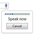
Simply click on the microphone and this should prompt you to speak.

Say the words “light on” and if the answer is right processing.php link will be opened. The browser records your voice input, it contacts Google Servers to do the translation into text for you, and the value will be put in the text field. The page processing.php will be opened if everything is OK as shown below:

Page showing LIGHT is on and voice message

In backgroung status.exe and edon.exe will be run for a short duration and a LED on the AXE050 will switch on. The processing page will automatically redirect to index.html page which will now show a live image of AXE050 with a LED switched on:

Main page shows a duly lit LED

If the command is not recognised you will prompted to say it again, as page alert.php will open and you will hear the robotic voice from Google saying “Oops! Try again!”:

Alert of Unrecognised Speech

The page will be shown briefly redirecting to main page index.html. If the command “light on” is repeated, even tough the LED is already on, the following page will be shown:

Already on alert and message

This page will redirect also to index.html.

Now try out the voice command “status” and the page will show the actual status of LED and local temperature:

Local status of LEd and temperature and message

Finally, try voice commands “light off”, “temperature” and “status” when light is both “on”! and “off”. If all is functioning correctly. all these voice commands will be recognised, and there will be interactivity when commands are repeated for cases such as of “light on” and “light off”.

Further work

More vocabulary  of voice recognition can be added improving speech recognition. Databases can be set up, not only to log issued commands, but also to obtain local conditons, and general status. Additional sensors can be added, such as humidity and light (LDR on AXE050 can be used to measure light at certain extaint). Graphs can be displayed, and trigger points set, adding support for email and/or sms when  events or alarms occur.

Conclusions

Voice recognition has been achieved and demonstrated using Google servers (that effectively are becoming Cloud voice servers), obtaining control and interactivity with a real world application. In less than a decade, voice recognition is starting to come to age, although is still not there fully yet. An exciting perspective that opens up, is the near future availability of speech recognition in mobile phones and more and more devices responding to voice commands.

Posted in Electronic Projects, Internet of Things | Tagged , , , , , | 8 Comments

Voice Operated Internet Control of a PICAXE (Part I)

Objectives

Experiment with speech recognition in order to control an electronic device remotely through Internet, and demonstrate new functionalities of Google Chrome 11 browser supporting voice-to-text and HTML5.

Introduction

In April 2011, Google released version 11 of the Chrome browser. One of the most important addition to the new version of Chrome browser is the support for speech recognition. One can enable speech recognition with a simple tag <input type=”text” xwebkit-speech />.

Google is effectively using the WebKit layout engine,  first released as a beta version by Microsoft Windows in September 2008, and the public stable release was released in December 2008.

The electronic setup

AXE050 board with Picaxe18M microcontroller is used. Picaxe products are manufactured by Revolution Education. Here is a picture of AXE050:

AXE050 Board

Note: AXE027 programming serial cable is required. Picaxe-18M uses the same port for programming and serial communication with PC.

The firmware in AXE-050 is the same as we used in Internet Control of a Picaxe (check the link). The idea behind using the same firmware without modifications, is to use it in future voice operated projects (if I get time for them…)

The main server

A Windows-based XAMPP server is installed in the PC. The server is hooked to a local network with a fixed local IP. The application is situated in a network that has no fixed public IP, hence DynDNS services is used. The router routes all external demands to the fixed local IP.

Windows XP and later do not allow easy RS232 control through Internet. To  overcome such a blockage, RS232 control is done through DOS, using Kermit for DOS. Kermit scripts are run by PHP, to control AXE050. Kermit’s executable MSK316.exe is installed in same directory as all files. They will be all in c:\xampp\htdocs (rename the servers default index page to another name)

Note COM2 is used  at baudrate of 4800 setup in Control Pannel of Windows XP.

LED ON Kermit script (name it ledon.ksc):


set port 2
set baud 4800
output c=n
exit 0

This script is called in a BATCH file (name it ledon.bat):


@echo off
c:\xampp\htdocs\msk316 take ledon.ksc
exit

LED OFF Kermit script (name it ledoff.ksc):


set port 2
set baud 4800
output c=f
exit 0

This script is called in a BATCH file (name it ledon.bat):


@echo off
c:\xampp\htdocs\msk31 take ledoff.ksc
exit

All batch files are then converted into .exe using Bat_to_Exe_Converter. So we will have two executables ledon.exe and ledoff.exe in the folder htdocs

Finally the html and php codes…

The html code is based on Romin Irani’s Voice Enabled Web Applications via x-webkit-speech example, that has been adapted to suit the requirements of this actual project.

index.html


<!DOCTYPE html>
<html>
<head>
<meta http-equiv="content-language" content="en-US">
<meta charset="utf-8">

<title>Voice Operated Control </title>
<script type="text/javascript">
function checkSpeechSupport(){
var element=document.createElement("input");
if (!('webkitSpeech' in element)) {
alert("Sorry! Your browser does not support the Speech Input");
}
}
function checkanswer() {
var answer = document.getElementById('q2answer').value;

if (answer == 'light on') {

window.location.href = "http://localhost/processing.php?action=on";
}

else if (answer == 'light off') {

window.location.href = "http://localhost/processing.php?action=off";
}

else {

window.open('http://translate.google.com/translate_tts?tl=en&q=oops!%20try%20again%E2%80%9D');

}
}
</script>
</head>
<body onLoad="checkSpeechSupport()">
<form id="speechform">
<fieldset id="inputs">
<font face="arial, verdana"><legend><h2>Voice Control of Picaxe AXE-050U:</h2></legend>
<label for="q2answer">Say "light on" or "light off" command:</label></font>
<input id="q2answer" name="q2answer" type="text" x-webkit-speech onwebkitspeechchange="checkanswer()"/><br/>
<img src="http://localhost:8888/out.jpg">
</fieldset>
</form>
</body>
</html>

processing.php

<?php
//check the GET actions variable to see if something needs to be done
    if (isset($_GET['action'])) {
    //Action has been requested
    //Issue the command we wish to send to the Picaxe
    if ($_GET['action'] == "on") {
        //Turn LED on - for this simple script we are just looking for either a 1 or 0
    $page = "script.html";
    header("Refresh: 2; URL=\"" . $page . "\"");

          echo "<font face=\"arial, sans-serif\"><b>LIGHT ON</b></font>";
          exec("ledon.exe");

     }

     else if ($_GET['action'] == "off") {
     //Turn LED off
     //Now we "open" the serial port so we can write to it
     $page = "script.html";
     header("Refresh: 2; URL=\"" . $page . "\"");

        exec('ledoff.exe');
          echo "<font face=\"arial, sans-serif\"><b>LIGHT OFF</b></font>";
      }

      }
?>

We are almost ready. We need to add video to the main index.html page, In the form section you will see http://localhost:8888/out.jpg. In fact we need to run a video server. Yawam is chosen to show a live image of the status of our AXE050 board.

YAWCAM

In order to view the LED switiching on and off a webcam setup is required. YAWCAM freeware is advised.  Having the requirements mentioned on the YAMCAM website one can easily establish a streaming server on port 8888. If the PC is behind a router the video streaming server port must be opened on the router.

Once YAWCAM is duly working you will need to enable Http and Stream in COntrol Panel of YAWCAM as the following image shows:

Http and Stream enabled

Trying out

We are now ready to open index.html. Point your Chrome 11 browser to http://localhost/index.html. Tou may now see the following (after you have directed your webcam to the AXE050 board):

Main Page Showing PICAXE050

Notice the little microphone shown at the end of the input text field. You will need a duly set up microphone in your PC (I have used an USB microphone). Do not write anything in the input field. Simply click on the microphone and this should prompt you to speak as shown below:

Chrome 11 prompting to speak

Once the browser records your voice input, it contacts Google Servers to do the translation into text for you, and the value will be put in the text field. Say the words “light on” and if the answer is right processing.php link will be opened:

In backgroung ledon.exe will be run for a short duration and a LED on the AXE050 will switch on. The processing page will be automatically redirected to index.html page which will now show a live image of AXE050 with a LED switched on:

Image shows a LED duly lit

If the command is not recognised you will prompted to say it again, as you will hear the robotic voice from Google “Oops! Try again!”. You can disable popup in your Chrome 11 browser if you don’t want popoups that you have to close.

Now we are ready to switch off the LED with voice command “light off”. If the command is recognised, processing.php will be opened again, and the following page will be shown:

In backgroung ledoff.exe will run for a short duration and the LED on the AXE050 will switch off. The processing.php page will be redirected to index.html page which will now show a live image of AXE050 with LED duly off, as we were in our first initial stage.

Conclusion

We have experimented with voice (speech) recognition. The technology has not come to age yet. One has different accents and pronunciations (mine is a big mixture 😉 ) and it is a huge task to recognise all of differing human voices. The interaction with devices adds an extra dimension to voice recognition. Chrome 11 browser’s support for speech to text is not well domumented. but gradually its potential is being discovered and shared.

NOTE: Check part II of this project!

Acknowledgements

A special thanks to Max Carter for sharing the orignail PICAXE firmware, and to Romin Irani for his above mentioned  index.html code (duly adapted for purpose of this project).

Posted in Electronic Projects, Internet of Things | Tagged , , , , , | 2 Comments

Fixing: Fatal Error Call To Undefined Function Json_decode

Introduction

On moving to my new CentOS server (with php version 5.1.6), the php code for automatically twitting latest posts from my forums to Twitter stopped working (check the php code here  A Twitbot Using OAUTH).

I will explain below how the errors were determined and fixed. This post may help others to fix a similar problem.

Determine the symptoms

  1. Enable error messages to be shown by writing ini_set( ‘ display_errors ‘,  ‘ 1’);  in your PHP code.
  2. If the error message is “Fatal Error Call to Undefined Function Json_decode ()”, read on…

The solution by installing JSON PHP Extension

1 . Ssh into your webserver with root privileges

2 .  Install gcc make:
# yum install gcc make

3 .  Install php-pear and php-devel :
# yum install php-pear php-devel

4 .  Install  json:
# pecl install json

If there are no dependency errors, or other, and all packages duly install you will next:
<

  1. Open your php.ini file  (ex. nano /etc/php.ini)
  2. Find in php.ini a section called Dynamic Extensions
  3. Add a line: extension = json.so
  4. Save php.ini and restart Apache (ex. service httpd restart)

You can check if json is enabled, installing in your httpdocs folder a php file (ex. test.php) with the following code:

<?php
phpinfo();
?>

If you open this page in your browser, you will see information on what your server’s php supports, and surely json will be one fo them:

phpinfo() showing json enabled

Finally test json, with following php code (ex. test_json.php) in your httpdocs folder as shown in  php.net website

<?php
$json = ‘{“a”:1,”b”:2,”c”:3,”d”:4,”e”:5}’;
var_dump(json_decode($json));
var_dump(json_decode($json, true));
?>
If you open the file in your browser, the result will be:

object(stdClass)#1 (5) {
[“a”] => int(1)
[“b”] => int(2)
[“c”] => int(3)
[“d”] => int(4)
[“e”] => int(5)
}
array(5) {
[“a”] => int(1)
[“b”] => int(2)
[“c”] => int(3)
[“d”] => int(4)
[“e”] => int(5)
}

Json_decode is now working in your server, and there will be no more error reports such as “Fatal Error Call to Undefined Function Json_decode()”.

Posted in Server Errors | Tagged , , , , , , | 42 Comments

A Simple Home Alarm System with DAQ and Labview

We all like peace of mind knowing that our home is safe when we are away, at work, or for whatever other reasons. The system here is a simple home alarm system with a motion sensor. The Labview virtual instrument (VI) described here can be easily expanded to a full-fledged alarm system with several sensors, and strategies of detection.

Objectives:

Design a simple alarm system using a PIR (Passive InfraRed) motion sensor that will detect movement on digital input of a DAQ device, and then output an alarm sound using the computer speakers,  sending at the same time a message of intrusion.

Background:

A Passive InfraRed sensor (PIR sensor) is an electronic device that measures infrared (IR) light radiating from objects in its field of view. PIR sensors are often used in the construction of PIR-based motion detectors (see below). Apparent motion is detected when an infrared source with one temperature, such as a human, passes in front of an infrared source with another temperature, such as a wall.(source)

Pre-Requirements:

Labview and DAQmx softwares  installed in your PC, and the DAQ device duly working, and recognised by Labview.

Required Equipment:

NI Labview 2010 Student
NI DAQmx 9.0.2
NI USB-6009 DAQ device
PIR movement sensor C-7288 or similar
Wiring leads


Basic Knowledge:

It is required to have basic knowledge in setting up a simple VI, such as the VI in the project Internet Control of a Labview VI.

The PIR Connections:

The Labview VI:

Build a Labview VI such as shown below. It uses an email SubVI that sends an email notification using SMTP service:

The Labview VI and all the components are available here, kept at Bitbucket, an unlimited free private repositories’ site.

Before Running the VI:

You need to have your DAQ Assistant function correctly set for your DAQ device. Check the above mentioned project Internet Control of a Labview VI.

Next, you need to open the Email_alert_subVI.vi contained in the zipped file just downloaded. You need to set up the SMTP details correctly.

Test the subVI running it, and checking whether you receive the email sent by the subVI. Please note that you have to be online to test the subVI.

 In order to make default the set up constants of SMTP, make current value default in the Block Diagram (e.g. for Sender’s Name constant, right click onto it with mouse, choose Data Operations, and next choose Make Current Value Default, and so on for each constant).

After setting up all constants, save the subVI, and open it, and check if the values you have chosen are shown on your subVIs’s Front Panel. Double check, testing again the subVI ensuring email is sent to you by the subVI.

How it works:

When running continuously the VI, the DAQ device detects motion with PIR sensor. The detected signal generates a 400Hz sinal that is sounded in your PC speakers, and the Intrusion LED on Front Panel of Labview VI is switched on.

The detected signal sends an email alert, using the subVI already set up by you with your SMTC account detals.

The alarm latches, and can be only stopped if you reset it by pressing the RESET button on the Front Panel. After resetting the VI will be ready to detect any new motion.

Tips and Tricks:

  • You can modify the VI in order log each intrusion time to file using a ‘Write To Spreadsheet File.vi’ express VI. There are plenty of examples on Internet on how to do it.
  • Expand your application by integrating more logic into the VI.  Possible scenarios might include a wait of a few seconds after clicking run to give you time to exit your home before the alarm starts to detect motion.
  • You can sent text messages to your cell phone using email to text servies (SMS) such as Clickatell, and many other such services. Normally these services are not free, but they are reliable. They all allow free credit to test your system.
  • You can add an arming feature with keyboard input such as the Home Alarm at Student Projects page  found here.
  • You can also add webcam as a motion detector and record any intrusion. You can find a tutorial with Yawcam. The system will send you also a text message (SMS) making use of a cheap webcam. Press here to see the tutorial.

Acknowledgments:

A special thanks is due to NI Developper Zone for inspiration. The actual project is based on article Dorm Room Alarm System Using a PIR Motion Detector, and following resources:


Posted in Electronic Projects | Tagged , , , , , | 17 Comments

Internet Control of a Labview VI (Part II)

In part I we have built a simple VI that controls a LED, switching it on or off through a virtual pressure button. We will now show step by step how to launch the application in the Internet and control it remotely.

STEP 23 –  Before anything else, we need to prepare the VI for multiple viewing. To do so in File menu we choose VI proprieties

A new window will open and in this select in Categories drop down menu Execution

A new widow will open and select Reentrant execution as shown in image

Press OK

STEP 24 –  Next we prepare the webserver. In menu Tools choose Options

In Options window, choose Web Server: Configuration

Enable server by clicking in the choice box on the right of the phrase Enable Web Server.

Press OK.

STEP 25 – Choose now Web Server – Visible VIs, and add switched_usb6009.vi as shown, in the field below the phrase Visible VI. Keep all other defaults as they appear

Press OK

STEP 26 – We will next prepare the webpage and launch it. Choose Tools -> Web Publishing Tool

In Web Publishing Tool window choose the VI

Press Next after the VI is selected

STEP 27 – Write the title and HTML content as suggested in the image

Press NEXT

STEP 28 – In the next window change the default name of the html file to index. Press Save to Disk button

A new window will open Document URL, press Connect button and then OK

STEP 29 – The webpage will be published and the browser will open

Now with the right button of the mouse placed onto the published VI choose Request Control of VI

STEP 30 – The grayed buttons of the image will now show up. Press the run continuously button

STEP 31 – Now press the virtual button on the VI

The virtual LED on the switch button will light up

The LED Circuit connected to DAQ device will also light up, having thus achieved remote control of the circuit

STEP 32 – Knowing the IP of the PC (and better fixing the IP)  one ought to be open the Labview’s page on the Internet.  If the PC is behind a router, one needs to make the adequate changes in the router, in order toall external demands to the local fixed IP.

One last thing

In order to view the LED switiching on and off a webcam setup is required. In order to stream video YAWCAM freeware is advised.  Having the requirements mentioned on the YAMCAM website one can easily establish a streaming server. If the PC is behind a router the video streaming server port must be opened on the router.

Conclusions

Having designed a VI we have controlled a real world circuit with a virtual button on the VI. We next have achieved Internet control of the VI using the tools that Labview offers.

Posted in Electronic Projects, Internet of Things | Tagged , , , , | 27 Comments