The PlayBook, as it is known Blackberry’s tablet, is the first device to run Blackberry Tablet OS, based on QNX Neutrino, and runs apps developed using Adobe AIR. It was later announced that the Blackberry Tablet OS would be merged with the existing Blackberry OS to produce a new operating system, Blackberry 10, that would be used universally across BlackBerry’s product line. A second major revision to the Blackberry PlayBook OS was released in February 2012.[3] The Playbook also supports Android OS applications, allowing them to be sold and installed through the Blackberry App World store (1).
Introduction
It is quite easy to design apps for Playbook, with recourse to Blackberry’s WebWorks SDK. Blackberry WebWorks for Tablet OS as the name “WebWorks” implies, is a platform for building deeply integrated web applications for the Blackberry PlayBook http://us.blackberry.com/developers/tablet/webworks.jsp. We are going to design a “Resistor Code” App with Blackberry WebWorks SDK.
What’s a Resistor?
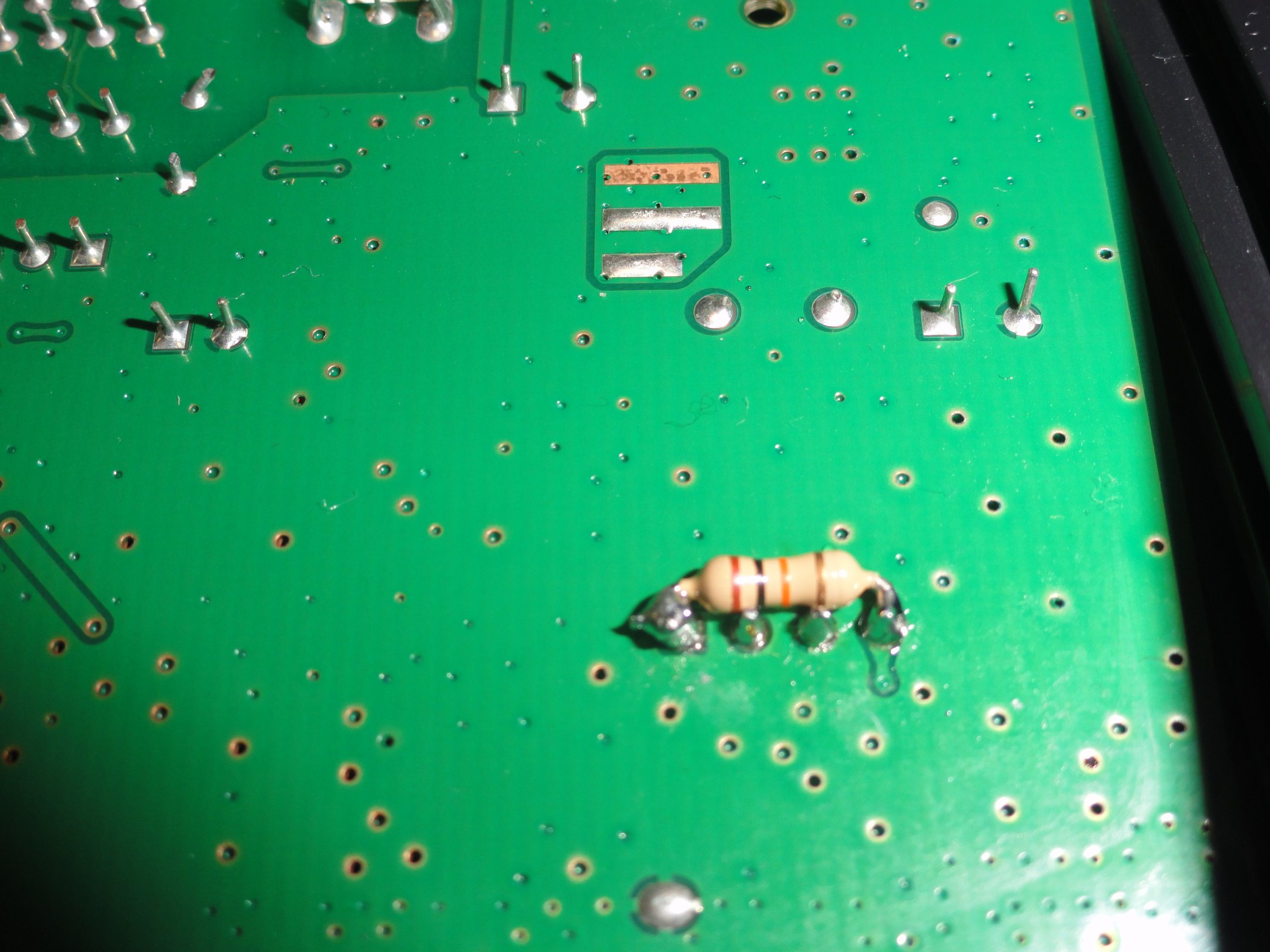
A resistor is a passive two-terminal electrical component that implements electrical resistance as a circuit element.
The current through a resistor is in direct proportion to the voltage across the resistor’s terminals. This relationship is represented by Ohm’s law:

where I is the current through the conductor in units of amperes, V is the potential difference measured across the conductor in units of volts, and Ris the resistance of the conductor in units of ohms.
The ratio of the voltage applied across a resistor’s terminals to the intensity of current in the circuit is called its resistance, and this can be assumed to be a constant (independent of the voltage) for ordinary resistors working within their ratings.
Resistors are common elements of electrical networks and electronic circuits and are ubiquitous in electronic equipment. Practical resistors can be made of various compounds and films, as well as resistance wire (wire made of a high-resistivity alloy, such as nickel-chrome). Resistors are also implemented within integrated circuits, particularly analog devices, and can also be integrated into hybrid and printed circuits.
The electrical functionality of a resistor is specified by its resistance: common commercial resistors are manufactured over a range of more than nine orders of magnitude. When specifying that resistance in an electronic design, the required precision of the resistance may require attention to the manufacturing tolerance of the chosen resistor, according to its specific application.(2)
What’s Color Code of a Resistor?
Color code is used to indicate the values or ratings of electronic components, very commonly for resistors, but also for capacitors, inductors, and others. A separate code, the 25-pair color code, is used to identify wires in some telecommunications cables. (3)
The electronic color code was developed in the early 1920s by the Radio Manufacturers Association (now part of Electronic Industries Alliance(EIA)), and was published as EIA-RS-279. The current international standard is IEC 60062.
Colorbands were commonly used (especially on resistors) because they were easily printed on tiny components, decreasing construction costs. However, there were drawbacks, especially for color blind people. Overheating of a component, or dirt accumulation, may make it impossible to distinguish brown from red from orange. Advances in printing technology have made printed numbers practical for small components, which are often found in modern electronics.
What’s a WebWorks app?
When you hear the words Blackberry WebWorks, think HTML5, JavaScript, and CSS. Essentially, a BlackBerry WebWorks application is a web application that runs on a BlackBerry smartphone or BlackBerry PlayBook tablet.
BlackBerry WebWorks is an open source project that you can find on GitHub. Be sure to check out some of the BlackBerry WebWorks Samples.
Why create a BlackBerry WebWorks app? Some reasons to consider are:
- portability
- integration with core BlackBerry apps
- ease of access, even when users do not have an Internet connection available(3)
Requirements
The creating of Playbook packages is done with not many external requirements. However, you need to use external tools in order to generate signing and debugging assets required to put deployments onto device.
Setting-up a Development Machine for Playbook Deployment
Blackberry Web Works SDK must be installed in order to obtain various tools required for obtaining certificates and device provisioning.
- Follow the instructions at https://bdsc.webapps.blackberry.com/native/ to download the SDK and any additional tools listed on the page.
- Install the SDK to your development machine.
I assume that you have the Development Machine ready by now as you proceed to next steps. If not, I recommend you set up the Development Machine before proceeding.
Code-Signing Keys
We will start by requesting a code-signing keys at https://www.blackberry.com/SignedKeys/. They are absolutely free!
Enter your name, company, email, country and a 6-10 digit “PIN.” Take note of the PIN since you will need it in next steps. I suggest you write down in a file named says “keys.txt” in a folder say named “BB”.
RIM will tell you to allow up to two hours in order to receive your code-signing keys by email.
When you are registered you will receive code-signing keys. You will receive a “PBDT” *.csj file, and an “RDT” *.csj file.
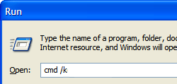
Now we can associate our own password with each of the code-signing keys. Enter into command-line of your PC , writting in your PC’s window in Start -> Run the command cmd/k
A full listing of DOS commands can be found at Wikipedia.
Next, in Command-line Terminal navigate to your Program Files with following:
bcd C:\Program Files\Research In Motion\BlackBerry WebWorks SDK for TabletOS 2.2.0.5\bbwp\blackberry-tablet-sdk\bin
If you know how to deal with DOS (check in previous paragraph Wikipedia’s link to learn about DOS commands) you can get there step by step. I advise you at this juncture to review your knowledge of DOS commands.
blackberry-signer -csksetup -cskpass (your password)
On my PC I did the following:
![]()
I have blurred my password. Take note of the password you have just made up, and keep it safe. You will require this password in next steps, and in the future.
Next run the following DOS commands using PIN and password you have just decided upon.
Registering “PBDT” *.csj file
blackberry-signer -register -csjpin (PIN) -cskpass (PBDT file)
Where the brackets are, you have to write your PIN and your PBDT csj file name, the latter is sent to you by RIM.
Registering “RDT” *.csj file.
blackberry-signer -register -csjpin (PIN) -cskpass (RDT file)
We are now ready to generate keypair which will allow us to sign our apps.
blackberry-keytool -genkeypair -keystore (output file) -storepass (another password) -dname "cn=(your company name)" -alias author
My key generating DOS command looked like the following:
![]()
I have blurred author, and other relevant information. I hope it will not be too difficult for you to do it .
We will now generate a debug token for testing the App we are going to design.
The debug tokens has *.bar file extension, so our output name will be like “debugToken.bar” or any other you choose.
N. B. You can create multiple debug tokens for each of your Playbook using “-deviceId” arguments. I am not so rich, so I have only one Playbook.
Find the PIN of your Playbook, after turning on the device, and swiping from the top of the screen down, to show the system preferences. Go to About > Hardware to find the PIN number as you see in following image:
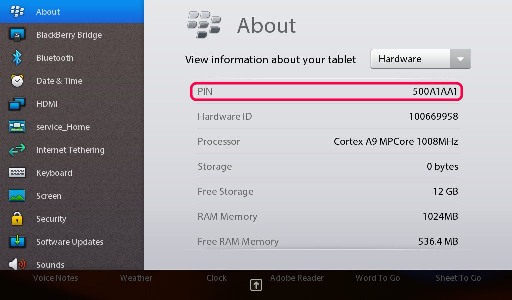
This is not my Playbooks’ PIN! I found this image on the web, and credit is due to the author of this image!
Next you will need to generate the debug token using this PIN:
blackberry-debugtokenrequest -cskpass (your password) -keystore (your keystore file) -storepass (another password) -deviceId 0x(your device PIN) (output bar file name)

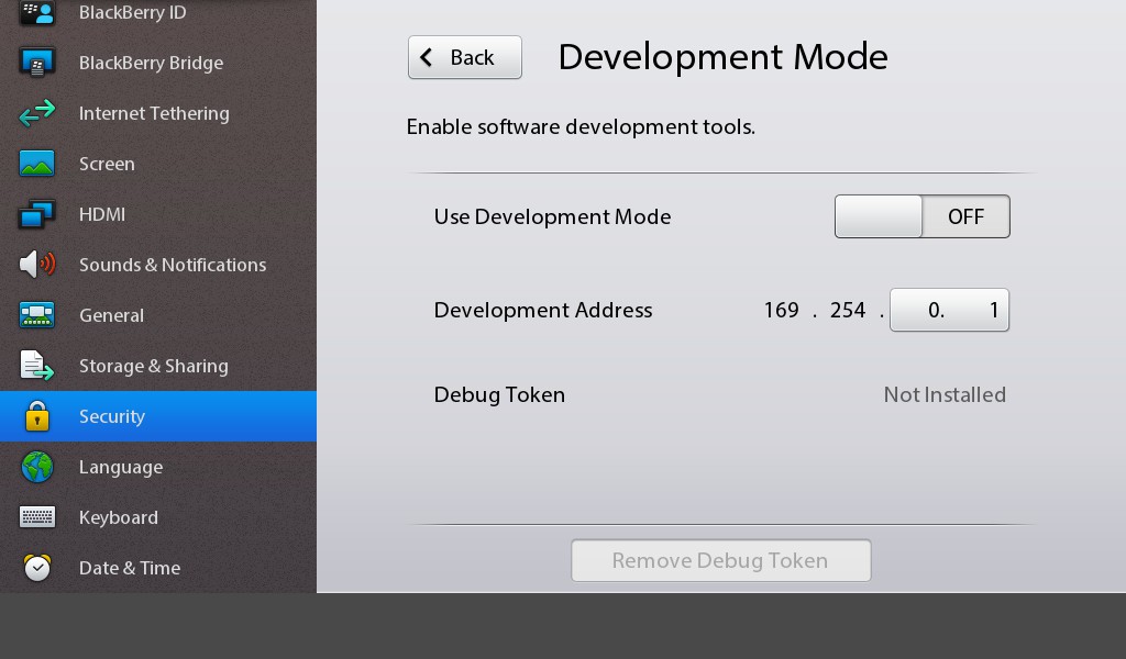
First of all connect your Playbook to your PC with USB cable (recommended), but you can also do it with Wifi. You will now enable your Playbook in Development Mode in Security > Development Mode from system preferences, and you will need to have yet again a new password which I suggest to be as simple as 123.
For Development Mode on your device, go to Security > Development Mode from system preferences. And set it ON. The following image shows “No debug token” and Development Mode is OFF.
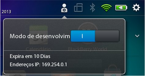
Take note of IP of your Playbook in Development Mode. We can certify the information on our IP in main screen of your Playbook, as show in following image of my Playbook:
Now we will install the token:
blackberry-deploy -installDebugToken (your debug token) -device (IP address) -password (device password)
Once you have uploaded your debug token with something like the following reassuring response you have reasons to be happy:
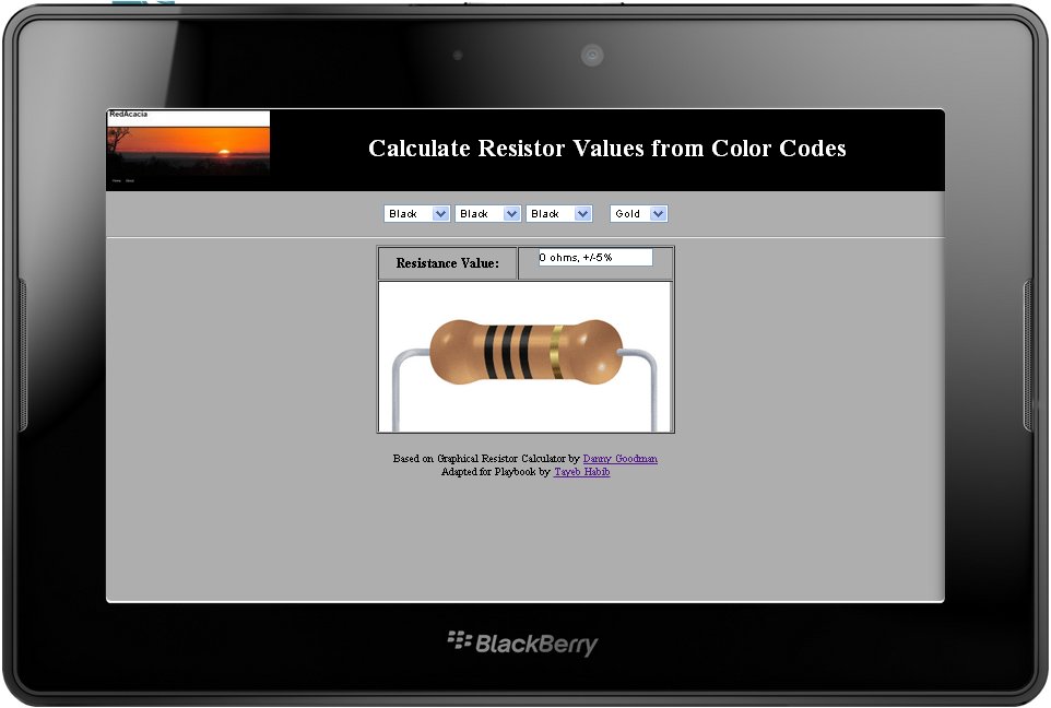
Preparing our App
We are now ready for our App. Our App will be a “Resistor Code Calculator” based on Danny Goodman’s quite old, and still popular, “Graphical Resistance Calculator”. You can view the web application and play with the Resistance Calculator visiting Danny’s site at:
http://www.dannyg.com/examples/res2/resistor.htm
I am proud owner of Javascript Bible that I bought many years ago from Amazon. Danny Goodman has authorised me to use his Javascript code to design our Blackberry Playbook App. The code we are using is quite old as old as my Javascript book. I don’t think the Javascript code has changed much, perhaps it has been fine tuned only.
In order not to reinvent the wheel, you will accept my zipped file “rescolor.zip” which you can download from Bitbucket, an unlimited free private repositories’ site.
Unzip the contents of zipped file. You will need an unzipper program perhaps. And now view the webpage (use Google’s Chrome as you will need it from now on). We are going to use the web app in the file to make our Playbook App.
You will notice there is a config.xml file in unzipped contents you have just downloaded. This file is required to compile our App.
You can preview how our App will look like on Playbook, by installing Chrome’s “Ripple” plugin. You can read about how to install it in Blackberry’s Developper pages.
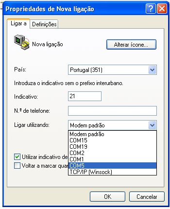
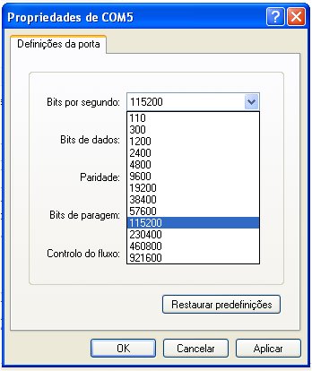
When enabled “Ripple” runs a web server on port 9910 of your computer. You will need to tweak Ripple in Chrome’s extensions (you can access “extensions” directly by pointing the Chrome browser to chrome://extensions). As shown in following image (in Portuguese, but I think it will be something similar in English) we have tweaked Ripple to view our PC’s URLs:
 Now open index.html in Chrome. In first run-time of Ripple, after enabling, it will be asking you the platform you want to run the page. Choose WebWorks-TabletOS (2.0.0). You will be next greeted with following image:
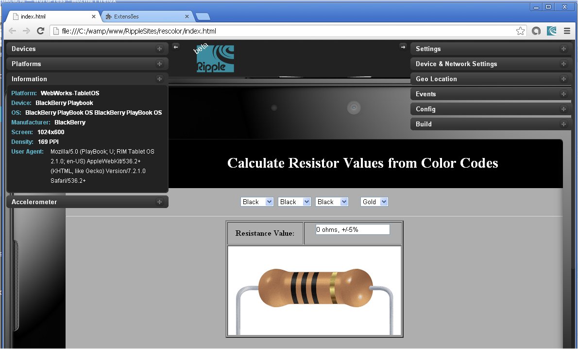
The left and right popups will allow you to configure your environment. I did nothing of that sort, as I was unable to start Ripple services due to problems with portuguese language characters of my Windows. I suggest you close the popups, pressing with the mouse onto two little arrows on top, pointing to left and right. You can zoom to view, within Chrome’s personalization (surely you know to do it!), and you will see our App in a simulated Playbook:
 We will next create a bar extension file of our zipped file (you just downloaded). If you have made any modifications to extracted files you will need to create a zipped file, that is if you want to implement your modded webpage.
So let us compile rescolor.zip and output as rescolor.bar. Return to DOS terminal as shown previously, to bbwp directory with following DOS command:
cd C:\Program Files\Research In Motion\BlackBerry WebWorks SDK for TabletOS 2.2.0.5\bbwp
To make it easy, create a directory myapp, and a sub-directory inside called output. Drop rescolor.zip file into myapp directory (or one that you modded) and run the DOS command:
bbwp c:\myapp\rescolor.zip -d -o c:\myapp\output
You will immediately get this inconvenient result shown by following image with a Warning and an Error:
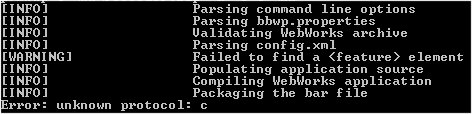
This error unknown protocol: c is what we need to sort out, as the Warning on feature is not so important at this stage.
To overcome this Error, you need to first create a temp directory in your C:\ drive (if you don’t have it already) and then issue the following commands in your DOS terminal
SET TEMP =C:\TEMP
SET TMP=C:\TEMP
This solution was found at Blackberry’s Discussion Forum. I did not find any alternative solution yet.
Now if you run the command again, you will get your compiled bar file in myapps/output directory. The following image shows these commands in my PC, plus the results of compilation:
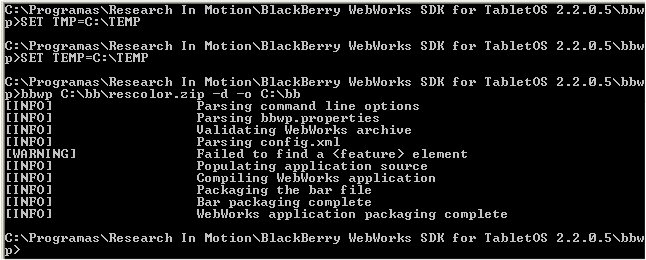
If you check your output directory, you will now find rescolor.bar.
Install and run the App
Now we will deploy this App in our Playbook. Navigate to tablet-sdk with the following DOS command:
cd blackberry-tablet-sdk\bin
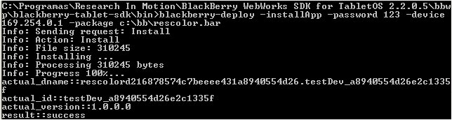
Run the following command to install the App:
blackberry-deploy -installApp -password 123 -device (your Playbook IP) -package c:\myapp\output\rescolor.bar
Hopefully it will install itself correctly, and you will get the reassuring output shown in following image:
You can now check your main screen and you will find the Resistor Color icon as shown on bottom left-side of the following image (these are actual screen shots of my Blackberry Playbook obtained by pressing simultaneously + and – buttons on top of the Playbook):
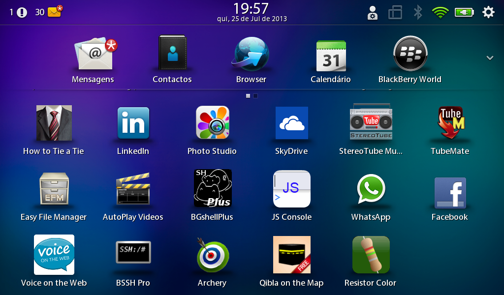
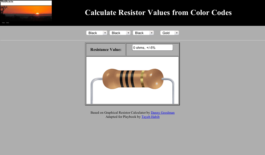
Run the App, and you can now play with color codes in your touch sensitive Playbook screen. The following image shows the App on my Playbook:
Acknowledgements
First of all thank you to Wikipedia for providing valuable information that I have used just about cut and paste at the beginning of this post. Also credits are due to Blackberry for providing so much valuable and free information on the Web. A special thank you is also due to Danny Goodman for his “Graphical Resistance Calculator” web application which has served to design our App. Also all credit is due to Joshua Granick for his easy to follow page on How to Create Keystore for Blackberry. Once more I thank Bitbucket for providing me a free of charge repository from where rescolor.zip can be downloaded.
Conclusions
As you have already seen, and tried (I trust) it is quite easy to write, and to deploy a webpage as an App. You can even deploy a weblink as can be seen in this App we have just designed which will open webpages within the App. The links at the bottom open Redacacia blog (this actual blog where you are!) and Danny Goodman’s webpage. If you have a “killer” webpage that you have written in Javascript, I bet you can deploy it as an App. Of course, in order to deploy in Blackberry App World Store, and to monetize with it, you will need to sign your App to make it publicly available, and you will have to take into consideration more issues surely.